hmm not really sure that the inside qualifies as an ugly amp, seems pretty neat in there...
/Chris
/Chris
MRehorst Scrapyard Boxed Amp
If it wasn't for that you have found that chassis in the "left overs"
your amp hadn't qualified among the Ugly.
But now it does - it is low priced enough.
Guess the soundquality place it among the great ones.
/halo
Scrapyard box like that! 😎MRehorst:
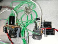
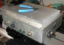
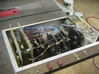
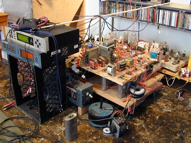
Here's my ugly amp, built into a box I picked up at a local scrap yard. The box is from a cellular phone base station diversity antenna amplifier (I think). It is 13" x 5" x 10". The walls and the base of the heat sink are 1/4" thick. The fins are about 1" high by 11.5" long.
I was able to use some of the existing holes in the box to mount the line cord socket, the fuse holder, and the input jacks. I filled the remaining holes with bondo, then drilled a few holes of my own for the power switch, volume control, and output jacks.
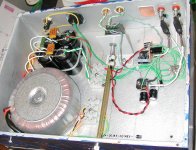
The nice thing about this box, besides the good size, massive amount of heatsinking, and ultra low price ($15) is that the walls are a separate piece from the top and bottom covers. To build the amp, I mounted everything on the heatsink (top cover), wired it up, tested it, then simply wired the connectors that were mounted on the walls.
If it wasn't for that you have found that chassis in the "left overs"
your amp hadn't qualified among the Ugly.
But now it does - it is low priced enough.
Guess the soundquality place it among the great ones.
/halo
This amp sounds pretty good, as I expected (it was designed by engineers, after all). No hum. No noise. No turn-on or turn-off thumps. It just starts playing when I turn it on and stops about 5 sec after I turn it off. After playing loudly for about an hour, my hand can just barely detect a slight temperature rise on the heat sink fins.
If you want to read about sparkling highs, lush midrange, and diarrhea inducing bass you'll have to go elsewhere. You'll get no meaningless listening test drivel from me.
MR
If you want to read about sparkling highs, lush midrange, and diarrhea inducing bass you'll have to go elsewhere. You'll get no meaningless listening test drivel from me.
MR
Hello MRehorst,
What is pretty good ? Did you compare it to other amps you have ? Is it better than you thought it would be and does it pay off to build one if you compare it to other DIY amps you've built ?
Maybe a short impression without meaningless listening test drivel 😉 I can do without a diarrhea inducing bass anyhow !
Regards,
Jean-Paul
MRehorst said:
If you want to read about sparkling highs, lush midrange, and diarrhea inducing bass you'll have to go elsewhere. You'll get no meaningless listening test drivel from me.
MR
Or you might try removing the 54,000 uF per side of the power supply capacitance and have another listen. 😉
Re: MRehorst Scrapyard Boxed Amp
Yes, it was cheap! I used standard 1% metal film resistors made by an unknown manufacturer. I think they cost me about 2 cents each, but I bought them in bulk a long time ago so I'm not sure. I did match them with my meter to insure equal gain in the two channels (though this was really overkill).
I used two bridge rectifiers because I had a pair of them in stock. I don't know the type or specs on them, but they turn AC into DC. I bypassed all four diodes with some 10 nF ceramic caps. I used a set of four 27,000 uF 35V caps that were available locally, and bypassed them with a pair of 1 uF polyester film caps. I put a 3.3K resistor across the supply to bleed the caps down to nearly zero within a few minutes of powering the amp off.
Most of the wire is silver plated copper with teflon insulation. I didn't use it because it "sounds" good. I used it because I have a lot of it which I purchased in bulk when I finally got tired of cheesy PVC insulation melting everytime I soldered a wire. The teflon stuff can take a lot of heat before it melts.
I tried using a triac to switch power but found that it caused the transformer to buzz, so I pulled it out and just wired the switch directly.
The output jacks are banana jacks chosen because the bolt that secures them is metal, not plastic, and because banana jacks are GREAT, low resistance speaker connectors. I think they are nickel plated, but I'm not sure. It doesn't matter. I spaced them so I could use double banana plugs on the cable ends.
The input jacks are very PC gold-plated, teflon insulated things that I bought in bulk in Japan for about $1 each a few years ago. The ground side of the jacks are insulated from the chassis and connect to the chassis only at the star ground point.
The volume pot is a detented dual 20K thing made by Noble. I got it in Japan for a few bucks several years ago. The two sections seem to track well which is good because I don't have a balance control. I hate mechanical pots and will replace this one with an electronic attenuator when I get around to it.
Let's see, box $15, xfmr $25, filter caps $10, I/O connectors $5, volume pot $5, misc. $20. About $80 in parts, total.
I didn't use any coupling caps, which is not a real safe way to do things, but my middle name is "dangerous". I don't recommend such a set up because any DC that shows up at the amplifier input will be amplified and sent to the speaker. Speakers don't like much DC for very long. I'll be adding coupling caps in the not too distant future.
halojoy said:
Scrapyard box like that! 😎
If it wasn't for that you have found that chassis in the "left overs"
your amp hadn't qualified among the Ugly.
But now it does - it is low priced enough.
Guess the soundquality place it among the great ones.
/halo
Yes, it was cheap! I used standard 1% metal film resistors made by an unknown manufacturer. I think they cost me about 2 cents each, but I bought them in bulk a long time ago so I'm not sure. I did match them with my meter to insure equal gain in the two channels (though this was really overkill).
I used two bridge rectifiers because I had a pair of them in stock. I don't know the type or specs on them, but they turn AC into DC. I bypassed all four diodes with some 10 nF ceramic caps. I used a set of four 27,000 uF 35V caps that were available locally, and bypassed them with a pair of 1 uF polyester film caps. I put a 3.3K resistor across the supply to bleed the caps down to nearly zero within a few minutes of powering the amp off.
Most of the wire is silver plated copper with teflon insulation. I didn't use it because it "sounds" good. I used it because I have a lot of it which I purchased in bulk when I finally got tired of cheesy PVC insulation melting everytime I soldered a wire. The teflon stuff can take a lot of heat before it melts.
I tried using a triac to switch power but found that it caused the transformer to buzz, so I pulled it out and just wired the switch directly.
The output jacks are banana jacks chosen because the bolt that secures them is metal, not plastic, and because banana jacks are GREAT, low resistance speaker connectors. I think they are nickel plated, but I'm not sure. It doesn't matter. I spaced them so I could use double banana plugs on the cable ends.
The input jacks are very PC gold-plated, teflon insulated things that I bought in bulk in Japan for about $1 each a few years ago. The ground side of the jacks are insulated from the chassis and connect to the chassis only at the star ground point.
The volume pot is a detented dual 20K thing made by Noble. I got it in Japan for a few bucks several years ago. The two sections seem to track well which is good because I don't have a balance control. I hate mechanical pots and will replace this one with an electronic attenuator when I get around to it.
Let's see, box $15, xfmr $25, filter caps $10, I/O connectors $5, volume pot $5, misc. $20. About $80 in parts, total.
I didn't use any coupling caps, which is not a real safe way to do things, but my middle name is "dangerous". I don't recommend such a set up because any DC that shows up at the amplifier input will be amplified and sent to the speaker. Speakers don't like much DC for very long. I'll be adding coupling caps in the not too distant future.
jean-paul said:Hello MRehorst,
What is pretty good ? Did you compare it to other amps you have ? Is it better than you thought it would be and does it pay off to build one if you compare it to other DIY amps you've built ?
Maybe a short impression without meaningless listening test drivel 😉 I can do without a diarrhea inducing bass anyhow !
Regards,
Jean-Paul
Well, I don't hear any readily identifiable distortion, and response sounds flat enough. Bandwidth seems adequate at both ends of the spectrum.
It pays off to build one if you need another amp, and I did.
MR
Peter Daniel said:
Or you might try removing the 54,000 uF per side of the power supply capacitance and have another listen. 😉
I don't think so. This is one of those things that I don't have to try to know if it works well. I know that the effect of removing the caps will be to increase the ripple on the supply and reduce the average supply voltage and thus the available power output. Increased ripple and lower power output are not advantages, in my humble opinion.
MR
You may be right and I never tried it myself, I just always used 1000u per rail. But since you have already 470u on ea. rail, it would be very easy to disconnect the main caps bank (52,000u) and hear what is the subjective difference in the sound, if any. I would imagine that anybody who's building gainclone based amp would be interested in that kind of observation.
Peter Daniel said:You may be right and I never tried it myself, I just always used 1000u per rail. But since you have already 470u on ea. rail, it would be very easy to disconnect the main caps bank (52,000u) and hear what is the subjective difference in the sound, if any. I would imagine that anybody who's building gainclone based amp would be interested in that kind of observation.
That would mean removing the 18 screws that hold the bottom cover on. Maybe in a week or two, when I've prepared a proper circuit board to replace the shabby wiring around the amps.
MR
UGLY Looking Amp! - but good working
😎 More pictures of Normal Ugly (but good) AMPS! 😎
PLEASE post a picture of your NOT so well looking AMP!
---------------------------------------------------------
Of natural causes, it is only the most "beautiful amps"
that get pictures posted. They are running the SHOW.
But surely they are only "the tip of an iceberg".
95% of All Good Great Sounding DIY-amps are REALLY Ugly.
Made up of materials recycled from scrapyards.
And simple chassis of thin, 1-2 mm Aluminium.
No fancy LEDs or Knobs.
---------------------------------------------------------
I want to see more of these AMPS.
More of the DIY everyday reality. 🙄
I could bet on that the amps that SOUNDS best
built by diyaudio members, are not very exceptionally looking....
/halo - has only built crappy looking amps
(Moderators: 😉 Any GOOD loooking Amp in this thread should go directly to TEXAS! 😉 )
********************************************************************
I guess a couple of 1000 more of them ugly beasts
have been built since we started this "contest".
Even Nelson himself knows how to build an un-attractive amplifier.
You can see it here below.
Nelson Pass' first Amplifier!!!!
Is this the ugliest one?
Or maybe you have a worse sample?
Bring it on!!!! You might take the price ... 😱
Attachments
this is ugly !!!!!!!
this one is ugly

and so is this
originally these amplifier pictures
were posted by ebrewste & Nielso
I am thinking of opening a
Gallery of most ugly looking amplifiers of this world
at my website
HaloAudio - for audio people who build themself
😎 would be a "the one of the kind" gallery 😎
this one is ugly
and so is this
originally these amplifier pictures
were posted by ebrewste & Nielso
I am thinking of opening a
Gallery of most ugly looking amplifiers of this world
at my website
HaloAudio - for audio people who build themself
😎 would be a "the one of the kind" gallery 😎
... but beauty is something inside a viewers head ...
sometimes broken things gets an added value
I say Picasso would have agreed, if he was still alive
otherwise than in his art
artwork below is called
"Mig Self"
/halojoy - has many times stressed the importance of Your Self - and to be true to that something -
which from another point of view is "My Self"
Attachments

"95% of All Good Great Sounding DIY-amps are REALLY Ugly.
Made up of materials recycled from scrapyards.
And simple chassis of thin, 1-2 mm Aluminium."
========================================
Daaaammm! How could it be so true and I didn't take a lesson!? I think it is because of the point to point wiring??? So for my tube pre-amp project being on progress, this time will be point to point! 😀
My first DIY amp was 17 years ago using broken cassete player I found on garbage can (The technician couldn't fix it so I tried my fortune). Made the housing from wood. The power supply was using a long series of batteries! The drivers were housed in empty milk can (of course it's empty!)
My second amp was an STK. Housed in a box made of thin aluminium plate. Took me weeks to resolve the grounding problem.
So sad that I cannot document that historical events...
Oh, and my first own amp design? Forget it, even the last one didn't work (Only after the internet era I had access to good resources of amp design, but I was too clever, I thought, if I could use expert's design for free why should I build my not-going-to-be-better own design? 😀).
Now I'm trying to develop my own methodology on designing speaker crossovers. This is quite different with the systems found on the book. I'm trying to find out the theoritical concepts to justify that methodology. Really wanted to post here and asked for consultancies from experts but was afraid everybody would laugh, or to be optimistic, was afraid anybody else would get the idea and develop the system for himself and won a noble prize 😀 😀 😀
[Sorry halojoy for the off-topic post]
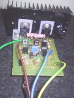
Here is the first version of my very ugly guitarcombo 🙂
with the poweramp:
Later I moved all circuits to the rack.
An externally hosted image should be here but it was not working when we last tested it.
with the poweramp:
An externally hosted image should be here but it was not working when we last tested it.
Later I moved all circuits to the rack.
- Home
- Amplifiers
- Solid State
- UGLY Looking Amp! - but good working