How to lower the power consumption of the 12V regulator transistors? Is there any resistor in series?
Res. in series?
I only can give the value for the 400 module. They are R59, 60 and are 1.2k @ 1/2 w. 30 volt 1 W znr's could be substituted to lower source voltage and impedance. Adding input caps to the transistors would be nice too if you can find room.
Roger
Bgt said:How to lower the power consumption of the 12V regulator transistors? Is there any resistor in series?
I only can give the value for the 400 module. They are R59, 60 and are 1.2k @ 1/2 w. 30 volt 1 W znr's could be substituted to lower source voltage and impedance. Adding input caps to the transistors would be nice too if you can find room.
Roger
good idea the zeners. When you have a 56V supply rail you have to waist, at 15ma, 56-12-voltage drop over resistors=15v, still30v so thats about 1/2 watt. thats why they get so incredibly hot these transistors.
Bgt said:good idea the zeners. When you have a 56V supply rail you have to waist, at 15ma, 56-12-voltage drop over resistors=15v, still30v so thats about 1/2 watt. thats why they get so incredibly hot these transistors.
Why is adding the zeners a good idea? It will not reduce the voltage drop over those transistors. It will reduce the voltage drop over the resistors but I don't think that is necessarily good, it will make the current flowing through the zeners more dependent on the power supply voltage as the voltage drop over the resistors is less.
Gertjan
A quick calculating tells you;
At 63VDC the voltage of the series resistor is 17V, current is 17mA. Dissipation of the 1k resistor is 0.29W (rated for 0.6W by 70C)
Voltage of the BDX transistor is 63VDC-17VDC-12VDC=34V. Dissipation is 34V*0.017mA= 0.58w.
Thermal resistance of an TO-220 to Ambient is 62C/W. So you will have a temperature rice of 36C, nothing to worry.
If you like to reduce the heat of the voltage regulator the best solution would be to use an extern power supply. This will probably even improve the sonic performance......😉
Jan-Peter
You're absolutely right. Forgot that you build up even more waist/heat.Why is adding the zeners a good idea?
If you like to reduce the heat of the voltage regulator the best solution would be to use an extern power supply. This will probably even improve the sonic performance......
Ofcourse that would be the best. But are there no riscs involved?
I mean the on/off timing maybe a bit changed. Is the other logic not fed by this 12V PSU?
Ofcourse that would be the best. But are there no riscs involved?
I mean the on/off timing maybe a bit changed. Is the other logic not fed by this 12V PSU?
When proper connected there will be no risk..
Remove the two TO-220 transistors, and connect the +12V on the emittor of the BDX33C and -12V to the emittor of the BDX34C. Ground on the Faston GND of the UcD400 board.
Jan-Peter
Wasted power
Sorry for the confusion. In my post I failed to state the idea was to replace the resistors with the zeners. By adjusting the zener voltage you can shift power dissipation away from the transistors. This means the zeners will be dissipating more than the original resistors and the transistors less but the total power loss will be the same. When zeners are conducting there source resistance is very low in comparison to a resistor. The actual value depends on the specific device being used but can be very low. This is what makes them useful as regulators.
By replacing the resistors (They are 1.2k, I rechecked) you have dramatically lowered the source impedance the regulator sees and have speeded up its response as well. This is due to shortening the R/C type delay. The disadvantage is that all the noise present on the main input is also coupled with this same lower source impedance and might be a problem. This is why I recommended a cap at the transistor input.
Roger
Re: Wasted power
Given that the regulator is a single transistor and the "input" merely its collector, I'd expect the difference to be quite marginal, especially since the reference zeners are decoupled. (I won't make any statements as to how marginal because at this time of day I'm too bleedin' lazy to go and check). Besides, resistors are cheaper to dissipating power into than silicon.sx881663 said:By replacing the resistors (They are 1.2k, I rechecked) you have dramatically lowered the source impedance the regulator sees and have speeded up its response as well.
A question about designing amps around the UcD400 modules.
I'd love to have RCA and XLR inputs. Is there an easy way to connect these both together, without some sort of switch?
I know I need to connect - and gnd together for RCA, but then I can't use XLR like I should.
Can't quite figure it out.
I'd love to have RCA and XLR inputs. Is there an easy way to connect these both together, without some sort of switch?
I know I need to connect - and gnd together for RCA, but then I can't use XLR like I should.
Can't quite figure it out.
Yves Smolders said:I'd love to have RCA and XLR inputs. Is there an easy way to connect these both together, without some sort of switch?
I know I need to connect - and gnd together for RCA, but then I can't use XLR like I should.
Mount the RCA electrically floating wrt. chassis. Tie RCA shell to XLR pin 3 and RCA signal to XLR pin 2. Then, if you want to use the RCA input, make a dummy XLR plug to connect pin 3 to pin 1 through a low resistance (you can try a resistance, a resistance in parallel with a capacitance or a dead short).
Besides, resistors are cheaper to dissipating power into than silicon.
So, can I just increase the resistor value to 1.8k/2k2 so the transistor doesn't dissipate that much heat. Does it have any influence on the sound?
Jan-Peter
Re: separate supply for driving regulator section ;what voltage would you suggest as ideal?
Curious,
Bob Lewis
Re: separate supply for driving regulator section ;what voltage would you suggest as ideal?
Curious,
Bob Lewis
It only powers the op amps and some CMOS logic. I'd say +/-12 (for the AD8620) or +/-15 (most other op amps).BOB LEWIS said:Re: separate supply for driving regulator section ;what voltage would you suggest as ideal?
I cant believe this problem has not been tackled before but I have seached this thread and elsewhere and I cant find the answer.
I am after a 42-0-42 230v Torodial Transformer about 500VA to power my 2 new UCD400's via the Hypex High Grade power supply.
I thouhgt it would be easy to find such a beast but I cant find them anywhere. I have checked Maplin RS Rapid and some other trafo sites.
Does anyone in the UK know where I can get one ??
Or have i just made a big mistake and sized the transformer wrongly?
In the uk we tend to have 250v mains so a 40v tranny might be better.
Farnell have ones for around £25
Farnell have ones for around £25
Farnell have a couple of 40V-0-40V 500VA parts listed with a 230V primary. (They are end of line stock, as the website says these will no longer be stocked, but they have some left).
One is a normal open toroid, the other is in a metal screening can as far as I can see from the pictures.
One is a normal open toroid, the other is in a metal screening can as far as I can see from the pictures.
Hello all,
I'm following (well, I try) this thread since a moment, and learned a lot.
I plan to build a 5 mono UCD400 amp, I will surely apply some basic tweaks on modules (capacitors replacement), but I actually have doubts about power supply.
Some said there are improvements choosing high quality components rather than other ones (fast rectifier, slit foil capacitors...), but I wonder if building a regulated PSU won't be more advantageous.
Many years ago, in a french diy magazine, a Hexfet based amp was using a regulated PSU, the autor believed in its superiority. But if it really is an improvement, why regulated PSU aren't used in diy project?
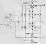
So I attached the schematics of this regulated PSU, I would be pleased that gurus tell me (us) what they think of it, and if it could be a good solution for UCD modules.
(note: this schematic was designed for a stereo amp, I suppose that one darligton per rail would be enough for one ucd400...)
Thierry
I'm following (well, I try) this thread since a moment, and learned a lot.
I plan to build a 5 mono UCD400 amp, I will surely apply some basic tweaks on modules (capacitors replacement), but I actually have doubts about power supply.
Some said there are improvements choosing high quality components rather than other ones (fast rectifier, slit foil capacitors...), but I wonder if building a regulated PSU won't be more advantageous.
Many years ago, in a french diy magazine, a Hexfet based amp was using a regulated PSU, the autor believed in its superiority. But if it really is an improvement, why regulated PSU aren't used in diy project?
So I attached the schematics of this regulated PSU, I would be pleased that gurus tell me (us) what they think of it, and if it could be a good solution for UCD modules.
(note: this schematic was designed for a stereo amp, I suppose that one darligton per rail would be enough for one ucd400...)
Thierry
Attachments
- Home
- Amplifiers
- Class D
- UcD400 Q & A