Just want to make the UCD 400 direct coupled by taking the 8620 output caps. out. Now I need to connect an input cap to the 8620. What is a good value and what kind of cap.? Are stacked polyester caps. ok for audio like the Epcos MKT series?
The input impedance is 100k to ground so if you want to set the corner frequency at, say 5Hz, that gives you a minimum of 330nF.Bgt said:Just want to make the UCD 400 direct coupled by taking the 8620 output caps. out. Now I need to connect an input cap to the 8620. What is a good value and what kind of cap.? Are stacked polyester caps. ok for audio like the Epcos MKT series?
I can't make any blanket statement like "stacked film caps are good / bad" because I've heard both excellent and terrible ones. That goes with most types of capacitor by the way 😀
On average, polypropylene caps sound better than polyester. Especially pulse rated ones are generally nice. Probably a constructional detail that correlates well with sound.
You might have a look at your preamp. If it has no DC (<5mV), you can do without coupling caps altogether. As they say, no cap sounds as good as no cap.
One channel power supply
Hi Bruno,
I wanted to build two monoblocks (for reasons due to cable), but I see that you only produce a 2 modules (ucd 400) high grade power supply for audio systems.
Do you plan to produce some power suply for only one module? I hope that...otherwise I have to spent money and time to build the psu with a possibly loss of quality due to my limited experience.
Also it would be great a kit if the final psu was not available.
Bye for now,
KEPha
the preamp is a passive 1 so it all depends on the inputs from the preamp which is a DAC(DC coupled) and other stuff. I think this will be a trial thing with some sorts of cap. Thanx
Inductor issues
Bruno, George,
Thank you for all that information. I now see why the sound is affected the way it is. When someone models all this it should show what values would be good to start with and what configuration would be best.
I never stopped to think about the situation when the diode goes reverse voltage and stops conducting. The energy stored in the leakage inductance has to go some where. Ringing may be only the tip of the iceberg. It also makes it clearer why ultra fast diodes prefer Zobels rather than just caps, gives that energy a path. One tends to treat transformers as an ideal part and disregard things like leakage inductance, obviously, doing so leaves problems hanging.
Nothing is ever simple when you get into it. The simplest parts of a simple circuit and due to nonideal component behavior it becomes quite complex. Of course at high frequency every thing becomes complex as these parasitics become dominant.
Roger
Bruno Putzeys said:
On average, polypropylene caps sound better than polyester.
Is it possible that you make more space to output cap next UCD version?
I mean that if LS10-15 cap can fit to PCP, it can give much more alternatives. Or is bigger LS cap somehow worse, even if PCP is designed with that?
Pasi P said:Is it possible that you make more space to output cap next UCD version?
I mean that if LS10-15 cap can fit to PCP, it can give much more alternatives. Or is bigger LS cap somehow worse, even if PCP is designed with that?
Well there's nothing wrong with having extra pin holes for larger caps. There's room enough to do that.
Bruno Putzeys said:
Well there's nothing wrong with having extra pin holes for larger caps. There's room enough to do that.
So, can we use LS10-15mm caps in current PCP. Only drill hole to fit cap?
Maybe it's late in the evening... What's PCP?
Anyhow, I mean that in a next version I could consider adding holes for optional larger caps (up to 15mm seems doable). Of course these holes need to be plated through and connected to the right traces.
Anyhow, I mean that in a next version I could consider adding holes for optional larger caps (up to 15mm seems doable). Of course these holes need to be plated through and connected to the right traces.
Bruno Putzeys said:Maybe it's late in the evening... What's PCP?
Anyhow, I mean that in a next version I could consider adding holes for optional larger caps (up to 15mm seems doable). Of course these holes need to be plated through and connected to the right traces.
Yes, it seems too late for me, sorry

Of course I mean Printed Circuit Board.. 😀
Thanks again, anyway 🙂
Roger,
So this is the reason behind this waveform?! It's already for a while that I was trying to find the mechanism behind it! Now you enlightened me, thanks!
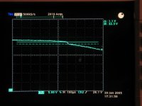
On the scopescreen there is visible the rectifier anode / transformer seondary node, at the moment of cutting off. The sinus is de-capped because of the voltage drop caused by the charge current on the secondary impedances [hm, suppose so..]
If I get it well this time, then the glitch visible in the moment of cutoff is because: the cathode tension is fixed by a low dynamic impedance at this moment [reservoir cap]. The diode is closing, so do not provide a path for the energy stored in the leakage inductance; so there develops that inductive back-voltage step [Lenz's Law] on the rectifier anode. This step sits on top of the [original] sinusoidal EMF induced in the transformer secondary.
This has nothing to do with reverse recovery currents; this happens with each type of rectifier.
Thanks, Roger, really!
I never stopped to think about the situation when the diode goes reverse voltage and stops conducting. The energy stored in the leakage inductance has to go some where.
So this is the reason behind this waveform?! It's already for a while that I was trying to find the mechanism behind it! Now you enlightened me, thanks!
On the scopescreen there is visible the rectifier anode / transformer seondary node, at the moment of cutting off. The sinus is de-capped because of the voltage drop caused by the charge current on the secondary impedances [hm, suppose so..]
If I get it well this time, then the glitch visible in the moment of cutoff is because: the cathode tension is fixed by a low dynamic impedance at this moment [reservoir cap]. The diode is closing, so do not provide a path for the energy stored in the leakage inductance; so there develops that inductive back-voltage step [Lenz's Law] on the rectifier anode. This step sits on top of the [original] sinusoidal EMF induced in the transformer secondary.
This has nothing to do with reverse recovery currents; this happens with each type of rectifier.
Thanks, Roger, really!
Attachments
I'm planing to built two monoblocks using the UcD400 modules and I have a couple of questions:
1) Adire recommands 400VA 45V. Should I use 40V for better protection?
2) Any benefit of using higher VA rating like Plitron's 625VA or 750VA?
3) Any suggestions for fast recovery diodes 10A 100V?
4) Adire recommands 9000uF per rail. I'm planing to use 3 Panasonic 8200uF 80V per rail. Any benefits or waste of money?
Thanks a lot!
I just asked quite a few of these questions a couple of posts back. Have a look there and also in some of the other UCD threads. "Easiest" way to search is to hit the print link (so it's all on one page) and then use the browser search buttons.
The suggestion given to me was to use MBR10100 for fast recovery diodes. Seem quite "cheap" as well. Also Bruno has given his thoughts on the right amount of caps in a couple of places and the punchline seems to be 10,000 per rail for a 4 ohm amp, but up to 20,000uF is ok (he recommended no more than that though...)
I think the higher Va rating is not likely to be that useful, but on the other hand it's quite cheap (incrementally) to go larger I think?
I have a Mark 1 UCD400 and suffer a fair amount of interference with my FM radio. I spoke to Jan-Peter about it a long while back and I'm just starting to implement his suggestion of self tapping screws to have better coupling between the heatsink and the board.
However, it only just occured to me that if this implies that the blue heatsink is supposed to be grounded to the case, then since I'm currently fixing the blue T using non-conducting thermal epoxy compound to a painted Alu case, then likely there is next to no grounding here at all!
To reduce RFI from my UCD is there a set of grounding rules to follow? In my case should I put a supplemental ground lead from the blue T to the star earth point?
I have tried some ferrites recommended by Jan-Peter on the speaker cables with negligible effect. Is it possible to use one ferrite on both cables, hence I could double up and put my two ferrites in series, both on both cables..?
Thanks
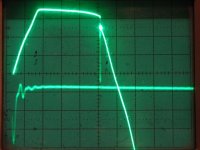
Snap back spike.
George,
Really nasty stuff! Lots of HF components in it and can couple into other circuits easily. Sounds like a line freq buzz but is very misleading as it is really almost all HF. A proper snubber will almost entirely cure this but instead of a voltage spike you now have created a current spike. This can also radiate into nearby stuff so you have to keep the leads short or at least twisted together. Remember the current path includes the transformer and its lead wires. Like Bruno says, “it’s in the details”.
Roger
Ps. Glad to have been of help!
Joseph K said:And this is what it looks like when there is also reverse recovery snap:
Ciao, George
George,
Really nasty stuff! Lots of HF components in it and can couple into other circuits easily. Sounds like a line freq buzz but is very misleading as it is really almost all HF. A proper snubber will almost entirely cure this but instead of a voltage spike you now have created a current spike. This can also radiate into nearby stuff so you have to keep the leads short or at least twisted together. Remember the current path includes the transformer and its lead wires. Like Bruno says, “it’s in the details”.
Roger
Ps. Glad to have been of help!
Power supply
Hi dears,
going back to the power supply project by Dejan Veselinovic on Tnt-Audio, surfing the web I found a new project by the same author
here it is (.doc + jpeg files)
http://www.zero-distortion.com/downlaod/universalpsu.zip
What do you think about?
KEPha
Hi dears,
going back to the power supply project by Dejan Veselinovic on Tnt-Audio, surfing the web I found a new project by the same author
here it is (.doc + jpeg files)
http://www.zero-distortion.com/downlaod/universalpsu.zip
What do you think about?
KEPha
Re: Power supply
But this one is not for power amp use, more for pre-amps since it can not deliver large currents and output voltage is also too low (can be modified of course but output current is limited).
Best regards
Gertjan
kephaudio said:Hi dears,
going back to the power supply project by Dejan Veselinovic on Tnt-Audio, surfing the web I found a new project by the same author
here it is (.doc + jpeg files)
http://www.zero-distortion.com/downlaod/universalpsu.zip
What do you think about?
KEPha
But this one is not for power amp use, more for pre-amps since it can not deliver large currents and output voltage is also too low (can be modified of course but output current is limited).
Best regards
Gertjan
Bruno Putzeys
I notice that the UCD700 has sparate power supply connectors for the regulated section;I presume that the UCD400 could be driven in the same fashion by removing the two voltage dropping resistors and fed with its own supply?
What would be the safe operating voltage range and are there any drawbacks to operating in this way if for example a fuse blew in the primary power supply?
Curious,
Bob Lewis
- Home
- Amplifiers
- Class D
- UcD400 Q & A