Jan-Peter said:The current limiter of the UcD400 starts to work at 15Arms or 21A peak. So there is not that big difference.
However why do you look only to the maximum current, do you listen to currents???
Any current limiting, even if ideal with no "sticking", sounds bad, whereas a little voltage clipping is hardly noticeable. With a rail voltage of 63 volts and a current limit of 21 amps, minimum speaker impedance should be at least 3 ohms to avoid current clipping.
A usually conservative rule of thumb to get a minimum impedance value for a speaker is just to use its dc resistance. A few so called 4 ohm speakers can dip down to 2 ohms or so and would thus be too low for limit free, clean sounding use with the UcD400.
Regards -- analogspiceman
Bruno,
Herw is my dilemma.................I use Sound-Lab M2 electostats that dip to below two ohms and are highly capacitive, on top of that they are rather ineffecient.
So I need 500w into 8 ohms .............will this be a problem for the upcoming UCD1000?
Regards,
Jam
Herw is my dilemma.................I use Sound-Lab M2 electostats that dip to below two ohms and are highly capacitive, on top of that they are rather ineffecient.
So I need 500w into 8 ohms .............will this be a problem for the upcoming UCD1000?
Regards,
Jam
I am planning to build UCD400 to drive my Linkwitz Orions woofers (two XLS10 connected parallel). Impedance minimum is about 2,5ohm. Is it too low to UCD400?
turning off
probably this has been already covered but I can't find the post , it's about turning off the ucd400.
a)I have pemanently the on connected to ground so I use only the main switch and when I turn off , after 20-30 second I hear a quite disturbing noise from the woofers is this normal ?
b)Is it aviodable using a switch on the on pin?
c)and in this case leaving the main switch pemanently on do I have any kind of voltage on the drivers and can I turn off the preamp and all the sources without problem?
d) Jan Peter when will be available your power supply?
Giorgio
Originally posted by Analogspiceman;
Any current limiting, even if ideal with no "sticking", sounds bad, whereas a little voltage clipping is hardly noticeable. With a rail voltage of 63 volts and a current limit of 21 amps, minimum speaker impedance should be at least 3 ohms to avoid current clipping.
A usually conservative rule of thumb to get a minimum impedance value for a speaker is just to use its dc resistance. A few so called 4 ohm speakers can dip down to 2 ohms or so and would thus be too low for limit free, clean sounding use with the UcD400.
In the current UcD modules we do not have a 'hard' current limiter, but a 'soft' current limiter. In a way the amplifier moves from a constance voltage source to a current soure, when the outputcurrent becomes above the setpoint. When you check the overload when there is too much current on the oscilloscope you see a nice soft limiting.
Originally posted by Pasi P
I am planning to build UCD400 to drive my Linkwitz Orions woofers (two XLS10 connected parallel). Impedance minimum is about 2,5ohm. Is it too low to UCD400?
No problem, we test all UcD400 on a load of 1 ohm, outputpower is still 200W and THD stays below <0.05%.
Originally posted by Giorgio;
probably this has been already covered but I can't find the post , it's about turning off the ucd400.
a)I have pemanently the on connected to ground so I use only the main switch and when I turn off , after 20-30 second I hear a quite disturbing noise from the woofers is this normal ?
b)Is it aviodable using a switch on the on pin?
c)and in this case leaving the main switch pemanently on do I have any kind of voltage on the drivers and can I turn off the preamp and all the sources without problem?
d) Jan Peter when will be available your power supply?
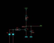
The best is to use an AC-detection and to switch the amp off when there is no AC anymore. You could use the schematic in the attachment.
On the two anodes you connect the AC of your transformer, any NPN transistor will be ok with an Hfe of >100.
Happy with the sonic performance on your horn systems?
Regards,
Jan-Peter
Attachments
Originally posted by Jam;
Bruno,
Herw is my dilemma.................I use Sound-Lab M2 electostats that dip to below two ohms and are highly capacitive, on top of that they are rather ineffecient.
So I need 500w into 8 ohms .............will this be a problem for the upcoming UCD1000?
Jam, please check this explanation from Bruno; http://www.diyaudio.com/forums/showthread.php?postid=617082#post617082
Regards,
Jan-Peter
Since everyone is chiming in and bidding on what Bruno should be doing with his time, here's my 2p (not sure when we became his employer, except by proxy, but hey)
New amplifiers would be great, and perhaps I would be tempted to upgrade one of my *four* stereo amps to some new fancy design.... But what I really crave now is some of the surrounding electronics like:
- powersupply boards (ok done)
- Pre-amp. I need an 11 way balanced volume control. Bruno, we already discussed this, and right now I have a DACT thing wired using one channel per balanced input with the hot and cold going across a single resistor - yes I also remember you telling me this wasnt a great design... Perhaps there is a way to integrate this with the power amp design if there is some advantage
- Digital input. Only if there is an advantage, a built in DAC in each poweramp would be interesting. Since I need so many it's not that convenient or neat to have a ton of outboard DACs.
Obviously one needs to put one's money where one's mouth is, but if you give me some serious specs on any of the above then I would entertain pre-ordering something today.
Feel free to ignore... Talk is cheap on the internet...
Congratulations to J-P and Bruno...
for this new alliance.
Thanks a lot to Bruno for designing these world class module amps, so easy to implement that even beginner DIYers can benefit.
😀 😀 😀
(Hey, this guy looks yunger than me 😡 )
I've built one 4 channel UcD amp (will become 2 stereo amps in the future), for an active system, that sounds better than any amp I 've heard before.
Needless to say that I followed every advice from both of you, gentlemen.
Now I'm expecting parts to build a pair of UcD400 (standard opamp ) monoblocks and run them in balanced mode from source to amp. I did some experiments with my present amp this way and the results were stunning!
I wanted to ask Bruno to make clear, if possible, some comments extracted from UcD180's thread and maybe useful in this thread:
*About PCords:
<<Actually it isn't necessary to use 3-wire mains cords. They only make sense if you have a mains filter with Y cap, and I have already advised firmly against those.>>
Yikk, is this safe?
*About "snubbers" in PSupply: (maybe UcDs don't need them)
<<UcD doesn't need any bypass caps on the main caps, simply because all bypassing has been taken care of on the module. No HF currents leave the module, so HF impedance of the power supply is inconsequential.>>
<<Other tricks are to use another, smaller elcap as a "damper" or "snubber". Should you ever have wondered what the 22uF small elcaps are doing on the UcD rails, there you are.>>
*What are the ideal bypass caps' type to use at the rectifier diodes???
*Other gurus find the 8620 opamp "thin in the highs". Any comments?
Best wishes...
Mauricio
I'd like to protect my speakers against the (unlikely) failure of an output MOSFET. I originally thought about inserting a DC-sensing circuit on the speaker outputs, but this would complicate too much my design (not to mention the space needed), since I'm dealing with a 6-channel power amp.
I've now resorted to putting fast-blow fuses on the power rails (+/- 60V DC), where each power supply feeds just one module.
How should I dimension the fuses? I'm confused by all the previous posts talking about the current capabilities of the UCD400.
Based on some calcs I did, it would seem to me that a 6A fuse per rail should be reasonable, but I'd like the comfort of somebody more skilled than me. Jan-Peter, what would you suggest?
Re: Congratulations to J-P and Bruno...

Serious disadvantage: Running I2S along ribbon cables produces a tremendous amount of RFI. It's quite tough to do that and still have radio reception.
If hypex were to put out preamps as well, wouldn't that take the Y out of DIY?ewildgoose said:- Pre-amp. I need an 11 way balanced volume control. Bruno, we already discussed this, and right now I have a DACT thing wired using one channel per balanced input with the hot and cold going across a single resistor - yes I also remember you telling me this wasnt a great design... Perhaps there is a way to integrate this with the power amp design if there is some advantage
Advantage: no more ground loop problems (at least on the analogue side - hum on the digital side comes out as jitter)ewildgoose said:- Digital input. Only if there is an advantage, a built in DAC in each poweramp would be interesting. Since I need so many it's not that convenient or neat to have a ton of outboard DACs.
Serious disadvantage: Running I2S along ribbon cables produces a tremendous amount of RFI. It's quite tough to do that and still have radio reception.
32. The picture was taken 5 years ago.maxlorenz said:(Hey, this guy looks yunger than me 😡 )
If you do choose to omit the earth connection you should of course adhere to the rules of double insulation.maxlorenz said:*About PCords:
<<Actually it isn't necessary to use 3-wire mains cords. They only make sense if you have a mains filter with Y cap, and I have already advised firmly against those.>>
Yikk, is this safe?
The damper cap is already on the module. For taming rectifiers recovery, any decent 47nF (one across each diode) or so will do. Make sure it's rated for the voltage.maxlorenz said:*About "snubbers" in PSupply: (maybe UcDs don't need them)
<<UcD doesn't need any bypass caps on the main caps, simply because all bypassing has been taken care of on the module. No HF currents leave the module, so HF impedance of the power supply is inconsequential.>>
<<Other tricks are to use another, smaller elcap as a "damper" or "snubber". Should you ever have wondered what the 22uF small elcaps are doing on the UcD rails, there you are.>>
*What are the ideal bypass caps' type to use at the rectifier diodes???
That would be the last attribute I'd attach to the 8620. However, AD sort of positions the device as a competitor for the OPA627. The OPA627 is very often rather cold sounding.maxlorenz said:*Other gurus find the 8620 opamp "thin in the highs". Any comments?
m.parigi said:I've now resorted to putting fast-blow fuses on the power rails (+/- 60V DC), where each power supply feeds just one module.
How should I dimension the fuses? I'm confused by all the previous posts talking about the current capabilities of the UCD400.
When you are building a 6-channel amplifier, providing fuses is a good safety measure, because the power supply will be 6 times as powerful as any one of the channels in isolation.
An amplifier delivering 400W into 4ohm running from +/-60V rails will draw around 3.7A (power+10% losses divided by 120V). 4 amp fuses will do.
I would not, however, recommend using fuses as a means for speaker protection. Suppose you have a 16 ohms speaker attached instead of the 4 on which the fuse rating is based. The fuse won't blow but the speaker will be fried anyway.
To make your life simple however, sum all 6 outputs together through 47k resistors and have only one DC detection ckt for this summed signal
input impedance
Is there a way to reduce the input impedance of the UcD400?
My pre-amp has an output resistance of 50 Ohm.
For a better s/n ratio it would also be better to reduce the impedance to 10k or less.
Just putting a resistor in parallel would waste a lot of signal.
The only drawback i could see is that the decoupling cap(if used) should be larger.
kees.
Re: input impedance
See an earlier response of Bruno in I believe this thread or UCD180 thread about the effective input impedance being that of the source's output impedance in parallel with the amplifier's input impedance which should give you a value of about 50 ohms.
kro5998 said:Is there a way to reduce the input impedance of the UcD400?
My pre-amp has an output resistance of 50 Ohm.
For a better s/n ratio it would also be better to reduce the impedance to 10k or less.
Just putting a resistor in parallel would waste a lot of signal.
The only drawback i could see is that the decoupling cap(if used) should be larger.
kees.
See an earlier response of Bruno in I believe this thread or UCD180 thread about the effective input impedance being that of the source's output impedance in parallel with the amplifier's input impedance which should give you a value of about 50 ohms.
Re: Re: input impedance
Exactly, so if your source is 50Ohm you don't have to do anything, you will have a low noise connection.
Gertjan
classd4sure said:
See an earlier response of Bruno in I believe this thread or UCD180 thread about the effective input impedance being that of the source's output impedance in parallel with the amplifier's input impedance which should give you a value of about 50 ohms.
Exactly, so if your source is 50Ohm you don't have to do anything, you will have a low noise connection.
Gertjan
Re: UCD400 in ballanced mode
Thank You bruno for your reply.
Still was hoping for some info about the maximum dissipation of the UCD400 in order to design the thermal aspects for UCD400 modules.
Another thing that I would like to know is the importance of the power xformer. IE in what way does the UCD400 load the power supply at full load?
63V powersupply will only just deliver 400W into 8Ohm. How sensitive is the UCD400 for voltage variations due to load?
What would be the max ripple voltage acceptable?
Thanks...Marcel
The eff. of the UcD400 is 93%, outputpower is 400W continous, so you need 430W of input power.
The PSRR of the module is >65dB. quite less sensitive for voltage variations.
Here some new info about the UcD400:
http://www.hypex.nl/classd/ucd400-1a.pdf
http://www.hypex.nl/classd/ucd400-1b.pdf
Regards,
Jan-Peter
The PSRR of the module is >65dB. quite less sensitive for voltage variations.
Here some new info about the UcD400:
http://www.hypex.nl/classd/ucd400-1a.pdf
http://www.hypex.nl/classd/ucd400-1b.pdf
Regards,
Jan-Peter
Hi Jan-Peter,
Those are nice informational sheets but little of that info is new, aside from some nice graphs.
However the one sheet (B, I think) seems to imply that layout is now non critical, which is also new information. So it sounds like now it's OK to mount one module right next to the other in a six channel amp and not suffer from any heterodyne issues.
Is this in fact now the case?
For now I'm still presuming there's no substitute for using a smart layout, and I think your customers would appreciate another informational sheet with such guidelines for a preferred layout and connection scheme as well (grounding + wire gauges etc).
Presented in a simple and clear way general public would be less intimidated by the DIY aspects of it. Having it on the FAQ would do fine also.
Thanks,
Chris
Re: Re: UCD400 in ballanced mode
63V will not deliver 400W into 8 ohm. With a bit of a stretch it'd just do 250. (Remember Rrms=V^2/2R)
Which means that as the power supply drops, less power becomes available in a quadratic fashion.
I tend to dimension the PSU for 10% ripple at max power but I'm aware that most people here prefer to err on the safe side and use larger psu caps.
(thermal question answered by JP)Tarasque said:Still was hoping for some info about the maximum dissipation of the UCD400 in order to design the thermal aspects for UCD400 modules.
Another thing that I would like to know is the importance of the power xformer. IE in what way does the UCD400 load the power supply at full load?
63V powersupply will only just deliver 400W into 8Ohm. How sensitive is the UCD400 for voltage variations due to load?
What would be the max ripple voltage acceptable?
63V will not deliver 400W into 8 ohm. With a bit of a stretch it'd just do 250. (Remember Rrms=V^2/2R)
Which means that as the power supply drops, less power becomes available in a quadratic fashion.
I tend to dimension the PSU for 10% ripple at max power but I'm aware that most people here prefer to err on the safe side and use larger psu caps.
UcD180/400
As i understand from reading about class D amplifiers the dead time is extremely important for the quality of sound reproduction.
Can anyone tell me what the dead time is for the UcD modules as compared to for instance Zappulse?
I believe they are fully discrete and i couldn't find any specs for it.
The dead time given for several different makes of class D integrated cirquits varies from 10 to over 600 nS.
The best i have come across is the TDA89xx family.(they use UcD i believe).
Dead time is the time both fets spend with VGS<Vth. There is also timing error (for lack of a better term) which is the variation in propagation delay over the full load current range. Both are often thrown in the same basket, but their behaviour is vastly different. I think the following answer is a bit more detailed than you signed up for but any time's a good time for popular education 🙂
There wood be only one reason to have dead time >0, namely to allow recovery of the stored energy in the parasitic and snubber caps. This can shave off more than half of the idle losses. This kind of dead time is very detrimental to THD though, and some modulators go crazy on it, because it constitutes a zone with reduced gain.
Timing error is related to the slope of the gate charge waveform. It is instructive to make a plot of propagation delay vs. output current. The smoother this plot, the lower the distortion introduced by this error. This means you don't need to shoot for ultrafast switching to make the timing error small, but rather aim to switch smoothly so the timing error becomes (ideally) linear with output current. The latter is of course a lofty ideal. In reality it can be made linear at lower currents but eventually it'll have limits regardless of current.
The Hypex modules have a few ns of dead time (design margin) and at full power the peak-peak timing error is 50ns.
The TDA89xx chips (most at least) are equipped with power stages that keep the peak-peak timing error below 10ns with actual dead time very close to zero. UcD's built using the TDA8938 or 8939 have pretty much the same distortion performance as the discrete modules, indicating that indeed minimising timing error is not strictly necessary as long as it is well controlled.
-
Not all TDA89xx are UcD's. In fact, only the unpublished TDA8938 was specifically intended for use with this control scheme.
- Home
- Amplifiers
- Class D
- UcD400 Q & A