CMRR?
Dean,
You are thinking! Yes unmatched caps would upset the CMRR but only where the differences were significant like less than 2 Hz, not much of a problem. The place it really matters is in the active circuits like the feedback caps that don't have an effect till several 10's of KHZ are reached. These being mismatched could cause a significant loss of CMRR at only a little above the audio frequencies. As they are controlling the gain small differences add up pretty quickly. They are usually very small caps and available to 1% tolerance so it is not much of a problem.
The test is to tie the plus and minus inputs together and drive them both with a 1 volt signal, measuring the output while sweeping the frequency. This is where you want as near to zero output as you can get. I have worked with circuits that had small trimmer caps to balance out stray capacitive effects to maximize the CMRR. Of course this was in a piece of precision test gear.
Roger
I'm drawing out the pcbs which will use a pair of double bridge MBR20200's so I can compare them against the pairs of KBPC04-25 too
Thanks Roger.
Sounds like I'm on the right path with my logic, I should attempt to get closely matched caps (auricaps) for the input but dont worry about it too much. I have 3 locations to place the coupling caps - at the input of the amp before the passive attenuator (2K serial resistance), after passive attenuator at the input of the UCD or between the UCD opamp and modulator. Am I correct in thinking that the cap should be driving the point of lowest impedence, which is after the passive attenuator before the UCD input?
As the amp will have DC protection, I'm considering putting in a relay to bypass the input caps completely and direct couple. If I do inadvertantly use a source with DC offset, I can arrange the DC protection circuit to fire the relay that breaks the input cap bypass so that the input cap is in circuit. This way if I use sources with no offset, I can enjoy direct coupling, assuming the relay contacts impart less signature than an auricap! Is this a reasonable idea? It makes sense to me but I have not seen this technique used before.
Regards,
Dean
deandob said:Thanks Roger.
Sounds like I'm on the right path with my logic, I should attempt to get closely matched caps (auricaps) for the input but dont worry about it too much. I have 3 locations to place the coupling caps - at the input of the amp before the passive attenuator (2K serial resistance), after passive attenuator at the input of the UCD or between the UCD opamp and modulator. Am I correct in thinking that the cap should be driving the point of lowest impedence, which is after the passive attenuator before the UCD input?
As the amp will have DC protection, I'm considering putting in a relay to bypass the input caps completely and direct couple. If I do inadvertantly use a source with DC offset, I can arrange the DC protection circuit to fire the relay that breaks the input cap bypass so that the input cap is in circuit. This way if I use sources with no offset, I can enjoy direct coupling, assuming the relay contacts impart less signature than an auricap! Is this a reasonable idea? It makes sense to me but I have not seen this technique used before.
Regards,
Dean
That's a great idea. Much more complex than a set of jumpers like the 700 will have .. the auto feature could be very useful if you're going to be using alot of different/unknown sources.
I think the cap should be driver the highest impedance, it allows you to use a smaller value/cap. Right before the op amps.
Regards,
Chris
Cool! A new idea! Except when the blocking cap is switched in circuit due to the DC protection, the DC disappears from the output, which drops the DC protection bypassing the input cap with the end result oscillating the relays. The only way this could work is adding a DC sensor to the input which is possible but more complex.
Opps. I did mean connect the cap at the highest impedance input not lowest....
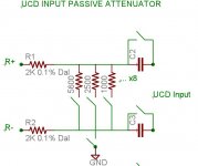
I think I have a fairly unique layout for the UCD input which allows me to use balanced & unbalanced inputs, a high quality passive attenuator driven by relays. The design goal here is to have the UCD input as high quality as possible through using as few components as possible (minimalist approach) and for those components to be as high quality as possible.
See the attached schematic:
- Negative inputs switched to gnd when using unbalanced sources
- Relays for shunt resistors driven by a microcontroller
- Input caps normally bypassed except when DC protection fired.
I'm not sure this circuit is optimal, as it might be better to bypass the negative input series resistor when using unbalanced sources (to reference the input source gnd not the amp gnd which this schematic currently does) and switching logic is needed so that the negative input cap is bypassed when using unbalanced sources. Or even better, bypass the negative series resistor and the negative input cap together when using unbalanced then the attenuation shunt to source gnd will include the 2K series resistor, as there is a relative volume difference between unbalanced sources and balanced (6db from memory?) then including the series resistor in the shunt circuit will help make up for the relative volume difference.
Is my logic sound?
Regards,
Dean
Opps. I did mean connect the cap at the highest impedance input not lowest....
I think I have a fairly unique layout for the UCD input which allows me to use balanced & unbalanced inputs, a high quality passive attenuator driven by relays. The design goal here is to have the UCD input as high quality as possible through using as few components as possible (minimalist approach) and for those components to be as high quality as possible.
See the attached schematic:
- Negative inputs switched to gnd when using unbalanced sources
- Relays for shunt resistors driven by a microcontroller
- Input caps normally bypassed except when DC protection fired.
I'm not sure this circuit is optimal, as it might be better to bypass the negative input series resistor when using unbalanced sources (to reference the input source gnd not the amp gnd which this schematic currently does) and switching logic is needed so that the negative input cap is bypassed when using unbalanced sources. Or even better, bypass the negative series resistor and the negative input cap together when using unbalanced then the attenuation shunt to source gnd will include the 2K series resistor, as there is a relative volume difference between unbalanced sources and balanced (6db from memory?) then including the series resistor in the shunt circuit will help make up for the relative volume difference.
Is my logic sound?
Regards,
Dean
Attachments
Hi Dean,
I'm not sure I follow all that but.. sounds pretty good. Are you positive you need that series resistor or just trying to make it as foolproof as possible?
I was wondering, why don't you make it more failsafe by ensuring that it is DC coupled firstly, and if it then detects low enough DC, say 5mV, or less, it can fire the relay and short out the caps safely, same idea really, but this way you never DC couple unless it's safe enough, and so the modules protection won't kick in.
You have to be careful not to leave yourself with a situation where unbalanced will automatically =DC coupling.
Try to keep the balanced/unbalanced logic independant of the the AC/DC coupling logic.
Regards,
Chris
DC protection?
Dean,
I am not sure I understand what you mean by DC protection. If you are referring to DC on the output what you propose doesn’t cover the case where an output device fails. I do like the Idea but see problems implementing it. You could use a more classic type of circuit for the main protection then have a manual switch for the bypassing chore. Or much better have close by relays do the job with the actual control switch anywhere you want. If the amps don’t turn on then flip the switch or if there is popping when you change volume levels then, once again, flip the switch or better yet replace the faulty source.
Roger
Chris,
My edit crossed your post, basically there is a flaw in my logic as the protection circuit will oscillate if I use the output DC to determine if I DC couple or not. A DC input detector will be needed, which would require an opamp due to the more sensitive input levels, adding to the complexity but not significantly.
I'll be using a microcontroller to control everthing so the more complex logic will be no problem (I have a software background).
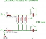
Am I correct about the volume difference between unbalanced and balanced and by adding the negative series input resistor to the ground shunt will make up for the difference? I have re-drawn the schematic if that makes it easier to read by removing the extra relay shunt to ground.
THis means for unbalanced sources, there will be no earth connection between the source earth and the amp earth except at the UCD input. Which may be a problem if there is a significant earth differential (the source is a SMPS in a PC, and the amp is on a dedicated mains circuit) or is this it a good thing not to tie the source earth & the amp earth together? I could add another relay (!) that shorts the negative UCD input to the start earth.
(edited to include image)
Regards,
Dean
My edit crossed your post, basically there is a flaw in my logic as the protection circuit will oscillate if I use the output DC to determine if I DC couple or not. A DC input detector will be needed, which would require an opamp due to the more sensitive input levels, adding to the complexity but not significantly.
I'll be using a microcontroller to control everthing so the more complex logic will be no problem (I have a software background).
Am I correct about the volume difference between unbalanced and balanced and by adding the negative series input resistor to the ground shunt will make up for the difference? I have re-drawn the schematic if that makes it easier to read by removing the extra relay shunt to ground.
THis means for unbalanced sources, there will be no earth connection between the source earth and the amp earth except at the UCD input. Which may be a problem if there is a significant earth differential (the source is a SMPS in a PC, and the amp is on a dedicated mains circuit) or is this it a good thing not to tie the source earth & the amp earth together? I could add another relay (!) that shorts the negative UCD input to the start earth.
(edited to include image)
Regards,
Dean
Attachments
Roger,
See my post just posted (crossed your post).
I want to bypass all caps in the input chain where possible, although my high end sources will only be balanced. You are correct, the DC input detection will need to be separate to the output DC protection to protect from UCD failure.
Its more complex but the ability to bypass DC coupling caps and still have versatility to connect different sources will be worth it.
Hopefully the sonic signature of relay contacts is less than an Auricap!😀
Regards,
Dean
deandob said:Chris,
My edit crossed your post, basically there is a flaw in my logic as the protection circuit will oscillate if I use the output DC to determine if I DC couple or not. A DC input detector will be needed, which would require an opamp due to the more sensitive input levels, adding to the complexity but not significantly.
I'll be using a microcontroller to control everthing so the more complex logic will be no problem (I have a software background).
Am I correct about the volume difference between unbalanced and balanced and by adding the negative series input resistor to the ground shunt will make up for the difference? I have re-drawn the schematic if that makes it easier to read by removing the extra relay shunt to ground.
THis means for unbalanced sources, there will be no earth connection between the source earth and the amp earth except at the UCD input. Which may be a problem if there is a significant earth differential (the source is a SMPS in a PC, and the amp is on a dedicated mains circuit) or is this it a good thing not to tie the source earth & the amp earth together? I could add another relay (!) that shorts the negative UCD input to the start earth.
Regards,
Dean
Hi Dean,
Actually I had the assumption you were thinking of detecting the DC at the input of the module from the very start . Depending what you MCU you use perhaps you can find one with an A/D converter to sense it with? Yeah it gets complicated alright... Seems it would only really be worth it if you could incorporate all the control through software.
I'd thought of using an MCU with mine for something else but I have to ask myself do I really want the noise of a clock signal in there?
I like Roger's idea... unless you want to produce them for the DIY market .... a switch is hard to beat.
You're dead on about the 6dB difference. From what I'm picturing if I understand this, I dont' think it would make up the difference so much as load the input down since it would be in parallel with the 100K input resistor of the module? But I'm not sure I follow that part at this time.
Chris,
Yes, the MCU I have has an A/D, so that part is easy.
I'm not sure about the analog side of things, I have redrawn the 2 scenarios, balanced and unbalanced. I dont think this is workable, as the extra resistance in the shunt will not allow for sufficient attenuation and I'm not sure about the grounding in the unbalanced scenario, if it is OK to connect the source ground at the input of the UCD and not to the star gnd.
If I go back to the original posted schematic, which had for the unbalanced scenario a shunt to the star ground, then the 2K negative lead resistor will be in series between the source gnd and the amp gnd - should be OK?
Regards,
Dean
Attachments

Hi,
I think you might be ok with the grounding because it goes right to the star point anyway.
I think you're probably about the resistor.
I think you might be ok with the grounding because it goes right to the star point anyway.
I think you're probably about the resistor.
Thanks for your help guys, appreciated.
I can use the MCU to compensate for the 6db level difference between unbalanced & balanced when attenuating.
Might be easier to use a line driver like DRV134 to convert unbalanced to balanced. The driver will add noise/distortion but unbalanced sources are not best quality anyway.
I'll breadboard both scenarios to try the theory out in practice. What is interesting about analog is with simple circuits there are still a lot of considerations to be had. With digital it either works 100% or it doesnt (most of the time) 😀
Regards,
Dean
Hi Dean I guess you're not using your soundcard as your source now?
Mine can compensate for the 6dB drop in the drivers for it, I thought your 0404 might do the same?
Mine can compensate for the 6dB drop in the drivers for it, I thought your 0404 might do the same?
Still planning to use a PC, best source around if done right. I'll either get the 1820M or the Lynx 2B, just waiting for one to come up on ebay stateside (too expensive in Australia).
Yes, the drivers can compensate for the drop, although I'd like the amp to do the compensation. Apparently the EMU Patch DSP processes in 32 bits, so for 16 bit sources you can attenuate by 16 bits without loss, which is pretty good.
Regards,
Yes, the drivers can compensate for the drop, although I'd like the amp to do the compensation. Apparently the EMU Patch DSP processes in 32 bits, so for 16 bit sources you can attenuate by 16 bits without loss, which is pretty good.
Regards,
Troubleshooting dead UCD400...
I just assembled a stereo UCD400 amp and only one channel works. The other has no blue LED on. Using common HG supply.
Thanks a lot for any suggestions on where to start...
I just assembled a stereo UCD400 amp and only one channel works. The other has no blue LED on. Using common HG supply.
Thanks a lot for any suggestions on where to start...
Re: Troubleshooting dead UCD400...
Assuming you double checked all your connections and voltages the next thing would be to remove the module and inspect it under a bright light with a magnifying glass. Look for broken surface mount components first and then solder bridges. Beyond this will take some real trouble shooting.
Roger
Regnad said:I just assembled a stereo UCD400 amp and only one channel works. The other has no blue LED on. Using common HG supply.
Thanks a lot for any suggestions on where to start...
Assuming you double checked all your connections and voltages the next thing would be to remove the module and inspect it under a bright light with a magnifying glass. Look for broken surface mount components first and then solder bridges. Beyond this will take some real trouble shooting.
Roger
Here is a quick thing to check if you are using the Hypex connectors. The ON (ground) wire was loose in one of the molex connectors I got. I ended up having to pull that wire out and just double it back in (not soldered to the female socket inside the connector at all, but pushed through the connector so it touches the pin directly. I had to fold it back inside to keep it from slipping back out when installing.
I started checking all of the stuff I put together and it took me a long time before I started looking at the other stuff, but that did fix my problem.
Jeremy
I started checking all of the stuff I put together and it took me a long time before I started looking at the other stuff, but that did fix my problem.
Jeremy
- Home
- Amplifiers
- Class D
- UcD400 Q & A