Hi Chris,
I'm a UK customer, so getting a couple of Plitrons is going to be fairly expensive. Curiously I also have a large commercial filtering unit which as far as I am aware is supposed to contain an isolation transformer... It's not working as well as the DC filter though for some reason?
Also I have now built everything onto the case and it's a bit of a squeeze, so I'm keen not to buy any larger torroids which would mean having to bin the case and redrill another one...
However, I don't think you are giving any secrets away by explaining how to size two diodes and a capacitor..?
By the way, you suggest bypassing the MBR10100, but I posted to this thread a few pages back and quite a few people suggested that this was unneccesary (and it seems quite a few people have built a similar design without bypassing). Is there a definitive answer on this? I thought the schottky was considered ok without a bypass...?
Thanks
ewildgoose,
Sorry to hear about your buzzing problem, i was not sure if you were saying that a single transformer buzzes when its on its own with the other one well out of the way?
I am going for a single 500VA rather than dual Mono and I have a potted transformer, it is very heavy and solid and I would be surprised if it buzzed, if nothing else works you might want to try a couple of potted trafo's.
By the way could you let me know what soft start you are using? I cound not work it out from the earlier posts.
Regards
Yeah, each transformer does buzz on it's own, but seems to buzz a lot more when both connected. I haven't tried reversing the primaries on one of the traffos, but is that a sensible idea?
The softstart is from LCAudio - seems to be a decent unit if a little expensive.
Ed
The softstart is from LCAudio - seems to be a decent unit if a little expensive.
Ed
Hi,
It's a diode, turn it off fast and there will be EMI generated, and those should turn off ultra fast. I can't recall where it got posted but I think Bruno recommended such a rectifier be bypassed with ~47nF just recently. 10nF might work fine too.
I don't know anything about the circuit from LC audio you mention, but there's another that sounds alot like it from PSaudio.
I also remember there's a thread about in the solide state forum where users first tried to ascertain its usefullness, and then reversed it, partially with the help of Paul from PSaudio.
Diodes like you're using in your bridge rectifier would probably be just right for the job, the cap was some sort of MOV (maybe.... foggy memory here).... it seems rather similar to the "ground lift" circuit you're seeing people using in the PSU schematics now.
Hope that helps.
Chris
Hey ewildgoose,
Are you still having so much DC that your protection is tripping?
This really doens't seem right. I too would like to know what you're doing for soft start, try removing it?
Perhaps there's another flaw with it as well, maybe you could post the schematic for us? Someone might spot a problem. A dual mono design that shares a soft start circuit? hmmmm curious.
Regards
Sorry, perhaps you are assuming more complication than I intended. Most of the specs are given in that LCAudio link I first mentioned. There is the circuit there and some parts listed...
I was more interested in why such a bit 22,000uF cap, when most people seem to be suggesting 1,000uF? What does ripple current mean and what kind of ripple current will I need?
There are a bunch of tranzil's on farnell, I think LCAudio suggests a 4.5V one, but the smallest I can see on Farnell is a 6.8V one. Is smaller better or worse for this purpose..?
Thanks
The tripping was traced to a damaged UCD400 board. Jan-Peter has been EXTREMELY helpful offlist diagnosing the problem and in the end I sent the board back to find that somehow I had ripped a small diode off the bottom of the board
I am using a single softstart for both transformers, but I don't really see why this would be a problem? 2x 500VA transformers?
Once the softstart is up and running I should have assumed it was quite similar to a straight bit of wire and hence irrelevant how many soft starts I use?
I am using a single softstart for both transformers, but I don't really see why this would be a problem? 2x 500VA transformers?
Once the softstart is up and running I should have assumed it was quite similar to a straight bit of wire and hence irrelevant how many soft starts I use?
In this case I'd think ripple current would be the spike it has to pass to charge your caps up each cycle. You should be able to roughly calculate it if you really need to, but it would be best to do like all other areas of the supply and just make sure it's built to handle alot, this I think is how you wind up with suge a big cap.
Here, I found you the thread I was talking about earlier, this doesn't seem to require such a huge cap.
http://www.diyaudio.com/forums/showthread.php?s=&threadid=37942&perpage=20&highlight=&pagenumber=1
If you want you can even find other renditions of the same circuit, it seems commonly known as a humbuster, DC trap, or DC filter.
BTW I hope you're not using this alongside your isolation unit? I think if you are, you'll need two traps, one for hot and another for neutral.
All this circuit does is AC couples your mains to your transformer right.....but only up to the forward drops of the diodes, then they begin to conduct. So the size of the cap is likely dictated by the ripple/load conditions. If you think about it, it would have to deliver enough charge to supply your reservoir caps, but only while the AC wave is withing +- the forward diode drop range, let's say 1 volt.
Given that I'd just guess that a 22 000uF is way on the overkill side, but what's wrong with that unless you're the one paying for it?
As far as diode selection I'd probably opt for some serious high end rectifiers like IXYS FRED 2X60 amp 600 volt puppies. You can go cheaper but cooling will be a factor and make sure they have serious current capability.
I don't even know what a tranzil is.... so I'm going to find out 🙂
Cheers,
Chris
ewildgoose said:The tripping was traced to a damaged UCD400 board. Jan-Peter has been EXTREMELY helpful offlist diagnosing the problem and in the end I sent the board back to find that somehow I had ripped a small diode off the bottom of the board
I am using a single softstart for both transformers, but I don't really see why this would be a problem? 2x 500VA transformers?
Once the softstart is up and running I should have assumed it was quite similar to a straight bit of wire and hence irrelevant how many soft starts I use?
You're likely right but.... it doesn't seem to be working very well and so.... I fish for possible problem areas? Usually it's the simplest little oversites that get ya. Maybe as a simple test you could try it without it?
Ewildgoose,
May I ask what is the actual configuration of your supply?
Dual secondaries or CT;
Toroid AC voltage, power, rectifier config, [dual or mono bridge], filter cap, DC supply value? For example, if you were using a single bridge with those mbr10100, with UCD400 voltages, then you are close to the edge... and the diode reverse current [cross-conduction..] might be a problem.. But if it were a dual bridge, dual secondary design, then should be Ok. [At least from this point of view]
Just my 2 cents worth..
Ciao, George
Schottkies bypassing?
Not necessarily a definitive answer, but I tried both: MBR10100 with 10nF bypass and without. Both work(ed) without any hum to be heard through (my) speakers (inputs shorted). That is clear, if you remember, that Schottkies don't exhibit recovery currents. On the other hand Schottkies have relatively large junction capacitances in the region of 1nF, which could act as a bypass too.
Here are the informative links again:
normal rectifier
fast rectifier
Yes, these are not Schottkies, but you may project the results onto them, I'm sure.
And, as I believe to remember, Bruno also suggested the bypassing for normal and fast rectifiers only, not neccessarily for Schottkies.
Best regards, Timo
By the way, you suggest bypassing the MBR10100, but I posted to this thread a few pages back and quite a few people suggested that this was unneccesary (and it seems quite a few people have built a similar design without bypassing). Is there a definitive answer on this? I thought the schottky was considered ok without a bypass...?
Not necessarily a definitive answer, but I tried both: MBR10100 with 10nF bypass and without. Both work(ed) without any hum to be heard through (my) speakers (inputs shorted). That is clear, if you remember, that Schottkies don't exhibit recovery currents. On the other hand Schottkies have relatively large junction capacitances in the region of 1nF, which could act as a bypass too.
Here are the informative links again:
normal rectifier
fast rectifier
Yes, these are not Schottkies, but you may project the results onto them, I'm sure.
And, as I believe to remember, Bruno also suggested the bypassing for normal and fast rectifiers only, not neccessarily for Schottkies.
Best regards, Timo
Just to be definitive, I think Bruno said to use a small RC network across the schotkies, values about 20 pages back in this thread in reply to a question from me. However, I *think* he was implying this was a nice to have and that they were "ok" without as well.
Others on this thread have built amps with the MBR10100 without bypassing. I don't own the equipment to comment, and the amp sounds really good (a fair bit better than my previous UCD400 design)
Others on this thread have built amps with the MBR10100 without bypassing. I don't own the equipment to comment, and the amp sounds really good (a fair bit better than my previous UCD400 design)
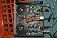
Here is a picture of my amp once I fixed the broken module which was shutting down, but before testing with any DC filtering. It's parked on the floor temporarily and the grill you can see is hiding 2x 15" Adire Tempest Woofers (and there is another pair just like it on the other side of the room...).
You can see more about my whole system here:
http://www.duffroomcorrection.com/wiki/User:Ed_Wildgoose
The situation at the moment is that the new amp using 4x 10,000uF BHC caps, MBR10100 dual bridges and 500Va torroids is sounding extremely nice. I haven't done a serious side by side comparison with the previous UCD400 that you can see on my web page above (single powersupply and half the capacitance), but on first listening it appears that you can turn it up louder before it sounds really loud and at lower volumes it's "easier to hear what people are saying". On massed orchestral pieces I get better ability to hear everything whereas before it went a little fuzzy when a lot was happening.
The only thing I am unhappy about it the buzzing from the transformers. It's on the bench at the moment being plugged into the normal mains supply. However, I was testing it before plugged into my commercial "KE" mains filter without any DC filtering (assuming that there was an isolation tranny in the KE which would have fixed it...). With the DC filtering it's "better", but still not quiet enough
Would it be totally stupid to consider carefully spraying the torroids with something like expanding cavity insulation foam... You know the stuff you get for filling big gaps in walls? How much heat will the torroids generate and will they be ok with a mass of expanded polystyrene stuff packing them in (or whatever this goo is made from...)
...Just a thought
Attachments
OOOOO I think that's a bad idea.
I think that will create an utter mess you'll really hate. I also think it will fail in your intent to have it hold the wires steady, it'll eventually work loose, probably sooner than later.
Plitron uses an Epoxy filler I'm sure you can find a few quarts of a similar product someplace to fill it with.
From plitron:
Insulation Primary to secondary:
Polyester tape, class B (130°C). 50 Hz transformers, four layers minimum. Meets the test requirement of >4 kV for one minute. 60 Hz transformers, three layers minimum, >2.5 kV for one minute. Interwinding secondary (where required) and outer insulation: Polyester tape, two layers minimum.
Temperature Rise:
Maximum 50°C. At maximum rated load, continuous.
Nice setup you have, I checked out your site. Is itthe RME that came with all in one wonder remote?
If you got your DC trap circuit to work but aren't satisfied..
Have you tried adding more series diodes yet?
I think there's some flaw that's got to be causing all this DC to begin .... something just seems abnormal about it. How is the supply while powered up with no modules attatched?
Transformers
Quite a few years ago when I was doing a 1000 W/CH amp for a pro sound company we went through a 1/2 dozen vendors to find one that could make a transformer that didn't buzz objectionably. This is basically a vendor problem and one of the ones we rejected was Plitron. The best of the bunch was Telema but this was before they were bought out by their present owners (Amvecco?). I can't vouch for there quality now and too bad as I don't know of any others with the possible exception of Avel Lindberg. I have used some of their lower power units quite successfully. There has to be a bunch of good units somewhere.
It seems the problem is core saturation due to being under spec.ed. This can be greatly exacerbated by even just a few millivolts of DC. With just a few milliohms of DC resistance it doesn’t take much DC to cause a lot of current flow. Then with loose cores or windings you get buzz. One of the parts that was particularly bad actually had stacked separate cores that were not tied down by anything other than the wire over them.
Roger
I have one more problem before I order some modules. My setup is going to be a two way speaker powered by the ucd, then I will have a set of stereo active subwoofers to cover the bottom end up to 80 hz or so. I would like to be able to use the same amplifier for all 4 amplifier channels (left and right, left and right sub amps) but the ucd only goes down to 20 hz or so. If I use a different type of amplifier for the subs, then due to the ucd's being digital, there will be a phase difference between the stereo subs and the main speakers. Is this a legitimate concern??
Chris8sirhC said:but the ucd only goes down to 20 hz or so.
I think the UCD will go as near DC as you like? I haven't measured it, but I have measured the Zappulse as being pretty flat down to around 10Hz or so *through the speaker*. I'm sure the UCD will go as low as you need them to.
In answer to the other questions, the LC audio DC filter uses a "tranzil", which appears to be the word for two diodes strapped together in opposite directions. The wording on the side of mine is 1.5Ke 6V8, which from the farnell site seems to be rated for quite a lot of DC. I'm not sure if I would get better results using two normal diodes, but I think the purpose of the diode is really to protect the capacitor, and I'm wondering if I actually need a *smaller* capacitor to reduce the amount of DC the amps sees, rather than a bigger one? At the moment I have a 10,000uF cap from Nichicon (I think?). I'm wondering if one with a few thousand uF would block more DC?
Basically using the standard LC audio DC filter *reduces* the humming but does not totally eliminate it. Also when I plug in both transformers the hum gets worse so I wonder if I should experiment with reversing the connection of one primaries (this shouldn't cause any problems right?)
Haven't had time to try any other experimets, but it's "only just" too noisy, hence the idea of damping the inside of the case with something easy like expanding foam. I don't expect it to stop the tranny humming, but it would probably reduce the noise level to something manageable, but I'm worried about overheating the transformer and fire risk..?
Basically I'm really close to having this finished and I'm trying to avoid a complete rebuild at this stage... I will see if I can get the potted transformers from Farnell to fit into the space I have got, but I have no guarantees that the potted ones will be any quieter right?
The ATI remote control that you can see on my website is available to buy seperately from ATI. (which is what I did). It's RF and not IR so you don't have to have line of sight. I actually also have a fancy VFD for my PC, but I can't see the display on the CD player etc from the seating position so I have done something unusual and routed control wires while the floor was up and I'm going to build a nice box so I can put the VFD on the coffee table...
The RME soundcard is very high quality and I can't hear any difference between it and my Meridan 508.24 CD player (hence the reason I don't use the CD player anymore). Actually I am sure there are differences between DACs, but I do think it's quite subtle and I have much, much bigger fish to fry like the room correction stuff which makes HUGE differences to sound quality. I think if I wanted to build a multiway active system using a PC for someone else I would just get the RME digital card and the external RME DAC. This gets you 8 decent channels for around 1000Euros and lots of capability for system matching (variable output levels on the DAC, etc)
This is where we come full circle. I think that the demands of digital correction are quite high on a traditional amp and can show up any deficiencies (try doing 6dB of correction in the bass with a traditional amp and you are stressing it quite a bit). Everything suddenly started to work better once I got these digital amps in place. (Thanks Jan-Peter)
Any thoughts on how to silence these wretched torroids would be appreciated though. Will try a smaller capacitor in the meantime.
Thanks
Hi,
I paid alot less for the same kind of features and possibly better performance by going with an emu 1820m sound card, for fully differential signals on all eight output channels, with dc coupling i/o.
While you're essentially AC coupling your mains with this you're only doing it by ~1.4 volts, if you use two diodes in series, or a 1.4volt transil/Transorb/TVS.. transient voltage surpressor. They typically handle alot of amps at come in various voltages, they're normally used in conjunction wtih at least a MOV, or I guess in this case a capacitor.
What happens is your AC signal rises from zero, a region where the diodes/transil etc isn't yet forward biased and so can't conduct, as it continues to rise in amplitude it obviously crosses their forward bias threshold and they then conduct the rest of that half cycle in accordance with the load. As it drops towards the zero crossing it again no longer has the potential to keep the "diodes" forward biased and they re enter a blocking state.
The opposite diode takes over the other portion of the AC, the negative half cycle.
This leaves with you with a band of about +-1.4 volts where no DC current can flow, and that's your level of protection. You can increase that protection by using a higher breakdown rating on your transil.
The capacitor's job is to AC couple the mains and supply current while the AC signal is crossing your dead band that the transil's impose.
So the higher you go with those probably the bigger the cap you'll need. I'd hate to see the size of the cap you'd require if you did away with the diode action all together and expected it to supply full load current at mains frequency..
You can also try using other caps /bypassing /parralel networks of different values in order to help smooth the transition from transil to capacitor too.
Also I don't think it would be sufficient to use just the one of these in the hot lead if you're using an isolation transformer because that would balance the mains signal.... they'd both be hot leads, could create a DC offset that'll saturate your transformers
Hope that helps,
Chris
classd4sure said:I paid alot less for the same kind of features and possibly better performance by going with an emu 1820m sound card, for fully differential signals on all eight output channels, with dc coupling i/o.
Does it have Linux drivers though? This is important to me since that's what I have based my system on...
With rgards to the other stuff the smallest "transil" that I can find is the one which seems to be used here (although Lars mentioned using any 4.5v one...). It's a "1.5ke 6v8 CA" which seems to mean a bit more than 4.5v worth of diode?
Anyway I am currently testing on the normal mains supply not the isolation unit and only filtering one wire right now. As you can see from the pictures above, fitting two DC filters in is going to be a bit of squeeze though. I would probably just build them inline into the inlet wires and wrap the capacitors in something insulating.
I don't really see why I would need two though? Surely DC is DC? It's a single primary so if you block the DC at one end then you block it at the other end as well yes?
Anyway, the point is that it's STILL humming even with the stuff above. So I need to try some more experiments to narrow it down, but I suspect that I will be into damping the case...
Thanks
Would it be totally stupid to consider carefully spraying the torroids with something like expanding cavity insulation foam... You know the stuff you get for filling big gaps in walls? How much heat will the torroids generate and will they be ok with a mass of expanded polystyrene stuff packing them in (or whatever this goo is made from...)
Although there are a few problems with spray foam (heat disipation, mess, corrosion?, etc.), I had another idea that I was contemplating using on my last UcD amp- Liquid Silicone immersion.
I came across liquid silicone when I was researching transformers and ended up on an industrial transformer site. High-efficiency, Low-noise power transformers (like what your power company uses) often use liquid silicone for cooling. The benifits are multiple: electrical insulation, chemically innert, natural vibration dampening, good thermal conduction. Has anyone tried something like this for an audio project? Could you submerge the modules also without damage?
I never tried it because I didn't want to take the chance with the modules and liquid silicone is expensive. I guess the enclosure would have to be like an aluminum tank. But maybe when I save up a little money...
- Home
- Amplifiers
- Class D
- UcD400 Q & A