ghemink said:
I think Jan-Peter has mentioned it somewhere that is was connected to GND via a capacitor. I just checked one of my UcD400 modules 4 you. It is indeed connected to GND via a capacitor (100nF according to my DMM).
Best regards
Gertjan
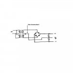
Does anybody know the value of L1-L6? These L's are there (at least that is my guess) to prevent or reduce the amount of HF noise leaving via the power rails outside the module. Also C16 and C17 are small decoupling caps directly at the + and - supply pins. With the L's they form a second order low pass filter at some frequency which would be interesting to know.
Best regards
Gertjan
ghemink said:
This is for sure not good. I advise to check the power supply first without any amps connected to reduce the risk of blowing up more parts than needed. Are you sure both transformers give the same output voltage? Be carefull with the power supply caps, what is their voltage rating? They should not be overloaded too much. If those big guys explode, you have a real mess., be careful.
Good luck
Gertjan
Well, I checked everything and it seems I had a couple bad capacitors. Transformers, rectifiers, etc were within .1 v of each other, but the voltage change happened when I hooked up the caps. At first, there was just a huge difference in voltage. Then, the + rail voltage increased when the amplifier was turned on until it tripped the overvoltage protection. Now I think I have two good caps and am reading 59v+-, but when I hooked up the amps, I get nothing, no led, no sound- nothing. Did I fry something? How could I tell/where should I look to figure it out?
If I ended up killing the amps because I used cheap surplus caps, I am not going to be happy... Somebody please tell me there is an easy fix.

Thanks,
Larry
lne937s said:
Well, I checked everything and it seems I had a couple bad capacitors. Transformers, rectifiers, etc were within .1 v of each other, but the voltage change happened when I hooked up the caps. At first, there was just a huge difference in voltage. Then, the + rail voltage increased when the amplifier was turned on until it tripped the overvoltage protection. Now I think I have two good caps and am reading 59v+-, but when I hooked up the amps, I get nothing, no led, no sound- nothing. Did I fry something? How could I tell/where should I look to figure it out?
If I ended up killing the amps because I used cheap surplus caps, I am not going to be happy... Somebody please tell me there is an easy fix.
Thanks,
Larry
Did you connect the /on pin next to the input pins to GND? If you don`t connect that pin to GND, the led will not go on since the amp will be switched off.
Hope this is your easy fix that you are hoping for.
Best regards
Gertjan
ghemink said:
Did you connect the /on pin next to the input pins to GND? If you don`t connect that pin to GND, the led will not go on since the amp will be switched off.
Hope this is your easy fix that you are hoping for.
Best regards
Gertjan
I checked the ground connection and it seems fine. Where else can I look? I'm thinking I knocked the voltage protection open and got it stuck. I assume it is some kind of relay- should I try to bypass it to test this assumption and then replace it if that is the case? how would I go about doing that? I obviously would rather replace a relay than an entire unit...
I don't know if this info helps, but when I powered down the amp after I tested to see if I could get the modules to light up, the capacitors discharged as if they had a ~1kohm resistor across them.
I was planning to eventually purchase a couple more units to biamp (I figure the ~1.5kVA worth of transformers will easily handle 4 ucd400s and I was going to buy new caps anyway), but I would really love to get the first two back up- both to save money and to get a chance to listen to them. I recently returned to work after being laid off for a couple months (the joys of advertising), so money is still a little tight. I am learning that cutting corners in some places (cheap caps) can end up costing more in the long run.
Thanks for all the advise so far...
Larry
Hello everybody,
I have just bought 2 ucd400 and 2 transformers of 2x45V (on load, 5% regulation , 46V mesured off load) by basing me on the specifications that adire recommends. is this too much? I am good to return it?
I had not read the beginning of this post which advises 2x38v rather 🙁
Or it s not to dangerous to use them because the overvoltage protection may work?
I want to use it for my subwoofer (15Hz-400hz) so i need much power
Thank you very much of your assistance
Best regards,
Avi
Heresis,
This voltage is quite high I recommend to go for 2 x 42AC. Supose the mains voltage is a little bit higher the amplifier will go very easy in overvoltage protection.
Good luck!
Regards,
Jan-Peter
This voltage is quite high I recommend to go for 2 x 42AC. Supose the mains voltage is a little bit higher the amplifier will go very easy in overvoltage protection.
Good luck!
Regards,
Jan-Peter
Thank you Jan peter for the reply 🙂 ,
So there is no way to reduce the voltage for 2-3v in the same way that the bridge rectifier do?
Or maybe can i modifie the overvoltage protection but then i will lose the garantie and is it dangerous for the ucd400? (if i change it to 66V)
Thank you very much, because that would be complicated to return my 2 transformers🙁
Heresis,
For bypass the overvoltage protection remove D19 and D20.
Of course you will not have guarantuee more.....
And mount the module not horizontal but vertical, this improves the airflow around the PCB.
Regards,
Jan-Peter
For bypass the overvoltage protection remove D19 and D20.
Of course you will not have guarantuee more.....
And mount the module not horizontal but vertical, this improves the airflow around the PCB.
Regards,
Jan-Peter
So I bypassed the overvoltage protection (thanks for the info Jan-Peter) and luckily, that (as far as I can tell) was all I damaged on the modules.
However, when I power them up I had the same problem as before- the positive rail voltage went up while the negative went down. Before, I figured it was just bad caps- but I wanted to check before I went out and bought new ones. What causes this? I'm not an engineer and this is my first project- so I have the feeling I am doing something wrong.
From the rectifiers, I am getting steady 59.5-59.7 volts DC on both rails with no load. The transformers are staying within .1v AC of each other. The positive rail's cap has the rail connected to the terminal labled + on the cap and the ground on the other terminal. On the negative rail, the ground is connected to the + terminal.
Both of the caps are on an alumunum shelf directly above the transformers. Would the proximity to the transformers do this? Unfortunately, the caps are huge (7"high x 3"dia each) and the transformers are huge (6.5"dia by 3.5"high each) and I don't have much room to move them within the 1cubic foot enclosure I built.
I will eventually be buying better caps, but I just want to check to make sure I am doing everything right first.
Thanks,
Larry
Can you put all +/- inputs to ground?
Because I think you have a problem with DC at the input. When the output of the amp has more as 100mV DC you will pump your power supply. I think this is your problem!
Jan-Peter
Because I think you have a problem with DC at the input. When the output of the amp has more as 100mV DC you will pump your power supply. I think this is your problem!
Jan-Peter
Jan Peter,
I had to work late last night, so I didn't get much chance to experiment. But I did try powering up with the inputs from the preamp removed- and I had the same problem.
With nothing connected to the input, the amp should not be getting any dc on the inputs, right? I'll try to connect them to ground tonight.
If it is not a problem with DC on the inputs, what else could it be?
Thanks,
Larry.
Larry,
Could you also measure the output of the amplifier. If the DC is below 75mV everything is ok.
Could you post your exact setup? (schematic?)
Jan-Peter
Could you also measure the output of the amplifier. If the DC is below 75mV everything is ok.
Could you post your exact setup? (schematic?)
Jan-Peter
power supply
line937s
You are using 2 transformers and one bridge rectifier right? This means you have to connect the transformers outputs together in some way, probably series right? Did you also connect this tie point between the transformers to the ground connection between the 2 caps? It sounds like you have a floating ground.
Sure would be nice to have a simple drawing of what you did. I really wished there were a share ware or free program to convert schematic drawings to jpeg or bit maps. Would be so nice to do a simple drawing and post it to show what I mean. Guess I can freehand one and scan it.
Roger
Attachments
Roger, that's what I do in order to share schematics in the forum:
Use your favourite electronics program (Protel, Orcad, etc) to draw the schematics. Then make sure that you see the portion of the circuit you want to show us, and capture the screen with the "Print" key (above the Insert, Delete, etc. keys).
Then open, for example, window's Paint program and paste, the captured screen will appear and then you can edit , cut and save what you want.
Hope this helps
Best regards,
Sergio
I hope this picture works- this is the first time I've tried to post a picture. I think this gives a better explanation of what I've done- sorry if I used any of the wrong symbols (I made it in Powerpoint). The rectifiers are just heavy duty potted type, bypassed by .047uF film capacitors. I left out the circuit breaker, power switch and soft start (just a momentary switch in series with some resistors bypassing the power switch), but I didn't think they would cause this problem.
Thanks to everyone for their recommended fixes- I am really anxious to get this working so that I can get to listen to what everyone has been raving about.
Thanks again,
Larry
Thanks to everyone for their recommended fixes- I am really anxious to get this working so that I can get to listen to what everyone has been raving about.
Thanks again,
Larry
Attachments
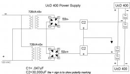
lne937s said:I hope this picture works- this is the first time I've tried to post a picture. I think this gives a better explanation of what I've done- sorry if I used any of the wrong symbols (I made it in Powerpoint). The rectifiers are just heavy duty potted type, bypassed by .047uF film capacitors. I left out the circuit breaker, power switch and soft start (just a momentary switch in series with some resistors bypassing the power switch), but I didn't think they would cause this problem.
Thanks to everyone for their recommended fixes- I am really anxious to get this working so that I can get to listen to what everyone has been raving about.
Thanks again,
Larry
lne937s, look at sx881663 last posted picture (circuit), I believe you are missing the ground from the transformer secondaries to the caps through to the ucd's.
Floating ground
lne937s
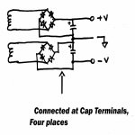
Connect the 2 points where the diode bridges are connected together to the common tie point between the caps and you have it fixed! To do it right the +/- of the bridges should be connected to the caps +/- terminals so the transformer charging current doesn't contaminate the common ground.
Like below.
Roger
lne937s
Connect the 2 points where the diode bridges are connected together to the common tie point between the caps and you have it fixed! To do it right the +/- of the bridges should be connected to the caps +/- terminals so the transformer charging current doesn't contaminate the common ground.
Like below.
Roger
Attachments
Roger/Chris
That makes sense- I'll fix it this weekend. I am realizing how little I know, but how much I've learned from doing this project and reading through this site.
I guess a picture really is worth a thousand words...
Thanks,
Larry
That makes sense- I'll fix it this weekend. I am realizing how little I know, but how much I've learned from doing this project and reading through this site.
I guess a picture really is worth a thousand words...
Thanks,
Larry
I just wanted to let everyone know I have it up and running- wow it sounds great on Magnepans!!!
Thanks to everyone for their help.
Larry
Thanks to everyone for their help.
Larry
lne937s said:Roger/Chris
That makes sense- I'll fix it this weekend. I am realizing how little I know, but how much I've learned from doing this project and reading through this site.
I guess a picture really is worth a thousand words...
Thanks,
Larry
I hate to be the party pooper but learning on the primary voltage is not a wise idea.
Before anyone plays with mains voltage they should have a TOROUGH understanding of electricity and electronics.
I fully encourage the learning and experimenting but not at the risk of personal harm.
- Home
- Amplifiers
- Class D
- UcD400 Q & A