More questions
Chris,
Ok, I can buy that but how in the world would you calculate the ripple current with the input going from rail to rail at the switching freq.? I am sure this is an important factor in determining core losses and copper losses due to skin effect. A true, pure, perfect inductor wouldn’t care about the di/dt or DC equivalent current. All I know for sure is the input square wave pk/pk voltage and the output voltage @ the switching freq. This output is close enough to zero to just call it zero for most calculation purposes. We could measure this residual switching voltage and with the ESR+ capacitive reactance get a pretty good idea of what the ripple current really is. If accuracy were wanted a small value resistor, one ohm or less, could be put in series with the ground leg of the cap and the measurements would be taken across it. If the inductors were perfect this would be no problem but with all the nonlinearities when pushed this hard it becomes a nightmare unless the residual ends up a very pure sine wave at the switching freq. I think this is why we just plug them in and try them. Is it because the square wave contains frequencies far beyond the switching frequency, in fact high enough to interfere with FM radio, that we can’t really get a handle in this? Should we be trying out RF rated cores?
I hope you can understand what I am really geting at here. I know my writing is not the greatest.
Roger
Re: More questions
Yes, for sure. It is RF after all!
I posted several times on this subject last year.
Core choice can change a lot of things in AF and RF. Most toroid cores used for swithcing power supplies aren't very effective above about 1MHz, or even lesss. But they don't need to be. A Class-D amp like the Tripath has RF harmonic on up past 10MHz. Cores optimised for these frequencies will do a better job at reducing RF.
But you still need to look at what the inductor is doing in the audio range. That's even more important. - right? 😉
sx881663 said:Should we be trying out RF rated cores?
Yes, for sure. It is RF after all!
I posted several times on this subject last year.
Core choice can change a lot of things in AF and RF. Most toroid cores used for swithcing power supplies aren't very effective above about 1MHz, or even lesss. But they don't need to be. A Class-D amp like the Tripath has RF harmonic on up past 10MHz. Cores optimised for these frequencies will do a better job at reducing RF.
But you still need to look at what the inductor is doing in the audio range. That's even more important. - right? 😉
Hi,
It is not difficult to calculate pp amplitude but you can put it more quickly in PSpice and simulate it.
Attached the result of the current through a 11 uH inductor at 60V_pp at 500 kHz. It is about 2.8 A_pp. It will halve at 1 Mhz and double at 250 kHz.
Btw the Micrometals Txx-2 cores have a mu_r of 10. That is pretty low (10 times the mu_r of air) and already suitable for RF up to 40 MHz according to Micrometals. That is quite different than the calculation Thomas did with the 160 mu_r cores.
Cheers 😉
Attachments
Micrometals has also design software for their cores. Attached the results for Txx-2 cores designed for a single layer winding. The total core losses differ not much for the different core diameters. Although AC inductance lowers for bigger cores, this is counteracted by the larger core volume regarding core losses.
Unfortunately it does not calculate copper AC resistance at the frequency of interest ??? So copper losses due to AC ripple current is not accurate, if they were taken into account at all.
😉
Unfortunately it does not calculate copper AC resistance at the frequency of interest ??? So copper losses due to AC ripple current is not accurate, if they were taken into account at all.
😉
Attachments
Pjotr said:Micrometals has also design software for their cores. Attached the results for Txx-2 cores designed for a single layer winding. The total core losses differ not much for the different core diameters. Although AC inductance lowers for bigger cores, this is counteracted by the larger core volume regarding core losses.
Unfortunately it does not calculate copper AC resistance at the frequency of interest ??? So copper losses due to AC ripple current is not accurate, if they were taken into account at all.
😉
Hi Piotr,
thanks for Micrometal's data. I tested already the T106-2 listed in your table.
http://www.diyaudio.com/forums/showthread.php?postid=977787#post977787
They are quite bigger than Bert's coils (T94-2) but sound worse, just like T68-2 and T80-2 used by Tripath and 41Hz.
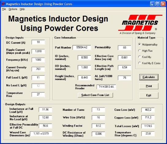
So I want to try Molypermalloy cores. Micrometal's SW gets no results selecting this material while Magnetics' one has many. The problem is that in their data input are required fields I don't understand:

10A and 1000khz are taken from Tripath's datasheet, while 1.818 ripple current from Micrometals software. With this values Micrometal's SW gets the right cores used by Tripath in their EV boards.
What values for the other fields?
Thanks
Thomas
Thomas, What makes you sure that your cores are from micrometals and mine are not ?
If you want to improve on inductors you should always use materials designed for the purpose. I think Mundorf coils have not been designed as RF chokes. MPP could be a good choice I think.
The no load inductance is the inductance without the DC or AF current superposed on the ripple. The temperature rise is how much hotter you allow them to become above ambient temperature. This will be calculated by the program at full DC current, which is not realistic in audio amplification.
Current density is probably the current per cross sectional area in the wire. 1 Amp in 1 mm wire gives 1.3 A/mm2, 130 A/cm2.
Groet, Bert
bertus said:Thomas, What makes you sure that your cores are from micrometals and mine are not ?
Because yours sound better 😀
You said you got them from CWS, aren't they core manufacturers? Have you their part number? My T106-2 come from a Tripath's EV board and the manufacturer is on the BOM.
Thanks for the data, I'll try MPP
Thomas
Hi Thomas,
Current density means the number of amps per unit area of copper wire. This defines the heating of the copper at DC (or low frequencies where skin-effect in negligible), it depends on the cooling by air flow. For 50/60Hz transformers it is between 2.5 and 5 A/mm2 for HF toroids as used in this application you can safely take between 10 and 20 A/mm2 ( --> 1000 - 2000 A/cm2). It sets the wire diameter at the specified DC current and allowed temperature rise.
The No Load L is the inductance at 0 A DC. At higher DC current the value of L lowers somewhat and the “No Load L” and the “Full Load L” set the boundaries you will tolerate, The effect of inductance variation due to DC current is lowest with the cores with lowest mu_r because the mu_r goes more to that of air. For high frequencies in the MHz range you will need anyway low mu_r, 160 is much to high. But play around with it and see what the core losses do.
“Temperature rise” is the rise temperature you will tolerate and will select the smallest core that can be used for that temp rise.
Cheers 😉
<Edit> I see, Bert was going me ahead 😉
bertus said:I think Mundorf coils have not been designed as RF chokes.
Hi Bert,
Dun no why they shouldn’t work? They obviously will radiate a lot of EMI but sonically …?
I did use these coils (50 uH) for a 1 KW flash tube and handled 2 KA pulses with ease and could stand 1.5 KV across them. 5 us pulses were no problem at all without running hot but they emitted huge EMI pulses. I had to can them with 2 mm soft steel 😀
Cheers 😉
Thomas, CWS winds coils, and buys its cores from micrometals, as fa as I know. This link gives more information
http://www.coilws.com/c_winding_main/Powder_Core_types.php
Whom to trust ?
http://www.coilws.com/c_winding_main/Powder_Core_types.php
Whom to trust ?
bertus said:Thomas, CWS winds coils, and buys its cores from micrometals, as fa as I know. This link gives more information
http://www.coilws.com/c_winding_main/Powder_Core_types.php
Whom to trust ?
I don't know. But if we go to MPP it doesn't matter.
What do you think of this?
So strange that with the same size of T106-2 and same 16AWG needs 13 turns instead of 29! I wanted this size (got it tuning the temperature rise) so I can use them on the AMP2 I'm building.
About Mundorf copper foil coils made for crossovers? It's just a try that costs 10€, as you can find them near home. With one 0.1mH coil (the minimum size I found) I can wind many 11uH coils.
Audio Research 150.2 and 300.2 use such coils with Tripath's TA0105A, so, at least, they can go. If I succeed will be very interesting the comparison with your coils.
Ciao
Giovanni
thomaseliot said:So strange that with the same size of T106-2 and same 16AWG needs 13 turns instead of 29! I wanted this size (got it tuning the temperature rise) so I can use them on the AMP2 I'm building.
Hi Thomas,
The difference is because of the permeability. The lower the permeability the more turn you need. For the Txx-2 cores permeability is 10 and for the selected MPP core it is 60. For the same size (roughly) the difference is sqrt( 60 / 10 ). Try a permeability of 26 or 14 and you will need more turns.
😉
Well, it may be worth a try.
But... there is a story that goes like this.
A higher permeability gives a saturation at lower current, and this also means that non-linear behaviour sets in at lower currents.
If I should do further experimenting, it would be with the lowest possible permeability, or air coils. The Mundorf coil is an air coil, but it may have mor stray capacitance, if that is an issue. I agree that Audio Research uses air coils, but my impression from the picture is that they are ordinary wire coils.
Success !
But MPP have all high permeability. The lowest is 14mu. Try that same size?
I'll take a better look to ARC coils..
Bert, you are right!

Well I'll try air coils too, but it is a deja vu (Charlize, Fenice, ecc.)
What kind of transformer they are using? The one visible must be for +5V and VN12 (that is our VN10).
I'll take a better look to ARC coils..
Bert, you are right!
Well I'll try air coils too, but it is a deja vu (Charlize, Fenice, ecc.)
What kind of transformer they are using? The one visible must be for +5V and VN12 (that is our VN10).
Hi Thomas,
Can second Bert, it is worth giving it a try. But if you order MMP cores (samples maybe?) I would try different permeabilities to see what it does sonically. So compare 14, 26 and 60 for the same core size. For that you can look them up in the catalogue pages and then select them in the list in the software to see what they will do.
It is true that higher permeability has more inductance modulation due to the audio current but how this will end up sonically? I really don’t know. After all I will not be surprised if you finally get best results with the Micrometal cores you already have. Very curious about…
As for the foil coils, my main concern is the large stray field they have. So there will be some HF coupling between the L an R coils and probably some feedback to other circuitry on the AMP board. But trying is the proof of the pudding here 😉 Good luck!
Cheers 😉
Thoughts on the subject
Hi guys,
Some thoughts I would like to share. The MMP material is very high in nickel content as are premium cores for coupling and output transformers. This is done primarily for lower distortion. Check the Jensen transformer web site for more on this. This could be an important part of the sonic performance.
Higher permeability is a plus if the core is still able to handle the flux density and not saturate. It means less turns and less copper loss, less turns mean less wire to radiate fields and act like an antenna. There is also the di/dt limitation to consider (inductance dropping off at higher frequencies). There are some other special ferrite materials that look promising and should be investigated. Ah, the art of compromise.
The foil wound coils will have a larger radiated field than ones that are fully shielded, true but with the main input being directed to the middle and the output connected to the outside it becomes an effective electrostatic shield. This won't help the radiated magnetic field so they would still need separation or mounting at an angle to one another.
Nothing is ever easy!
Roger
Hi Roger,
thanks for your usual clear synthesis of the problems involved.
Just ordered from CWS the MPP, sized as shown in the previous picture (OD 1,060, 60u).
Copper foil coils 0.10 mH arrived from Mundorf. I've to unwind them to get 11 uH, but I'm waiting for a LC meter.
For the radiated magnetic field of foil coils, I've read they are mounted in crossovers one perpendicularly to the other, with the center of cores in axis.
Let you know
Ciao
Giovanni
thomaseliot said:Just ordered from CWS the MPP, sized as shown in the previous picture (OD 1,060, 60u).
Hi Thomas,
IMHO you can do with a smaller one of app 0.8 OD but anyway:
Why not order 14 and 26 permeability either so you can compare them?
Cheers 😉
Pjotr said:
Hi Thomas,
IMHO you can do with a smaller one of app 0.8 OD but anyway:
Why not order 14 and 26 permeability either so you can compare them?
Cheers 😉
Hi Piotr
I ordered them from CWS online and they had 60u only: it is the only site I found selling small quantities. 1.060 OD is the same size of cores of the AMP2 I'm building.
Where do you get samples?
Ciao
Giovanni
- Status
- Not open for further replies.
- Home
- Amplifiers
- Class D
- UcD180ad Vs 41Hz Audio AMP5 (Tripath TA2022)