Re: Re: Re: input coupling caps
I see no reason why to use 25V caps. These are coupling caps, there would hardly be any voltage over these caps, so probably even 6.3V is OK. I guess best would be to use the non polarized caps, NX or NX-HiQ?
By the way, with the AD8620, I think you don't need them as long as your preamp has no DC at the output.
Best regards
Gertjan
mac said:
Thanks Gertjan. My boards did have the NE5332 but I just upgraded them to AD8620 🙂. Do you think a 25v rated cap would be adequate? Cheers, mac.
I see no reason why to use 25V caps. These are coupling caps, there would hardly be any voltage over these caps, so probably even 6.3V is OK. I guess best would be to use the non polarized caps, NX or NX-HiQ?
By the way, with the AD8620, I think you don't need them as long as your preamp has no DC at the output.
Best regards
Gertjan
With the AD8620 there is no need for coupling caps after the OP-amp. If you wan't to protect the amp from DC from your pre-amp, you should instead palce some high quality film capacitors BEFORE the OP-amp as the impedance here is much higher, meening the capacitors can be at least an order of magnitude smaller and still have the same cut off frequiency. Two 1 uF WIMA MKP10 or similar would do the trick.
Koldby
Koldby
Re: RMAA test of UcD180
Hi Timo,
Just scanning this forum for some time, but I wonder whether you have already some more info over the RMAA test.
I'm not worried over the roll-off, but quite astonished over the amount of distortion you measured.
I can hardly believe this amount has anything to do with the quality of your load, however I assume that spurious signals into your measurement equipment blew the results
Ever had any comment from Jan-Peter over your measurement?
Regards,
Arthur
tiki said:For those, who are interested,
I played a bit with an external soundcard (Terratec Phase 24FW) and used it to perform a simple test with one channel of the UcD180 amp. Please don't ask for the conditions, the wiring was horrible, at least from the output of the amp. The input was connected via a balanced 6.3mm/XLR-adaptor and 5m XLR low noise cable.
Here are the RMAA results.
I would not rely on the results, but for a first impression it should be okay.
Regards, Timo
Hi Timo,
Just scanning this forum for some time, but I wonder whether you have already some more info over the RMAA test.
I'm not worried over the roll-off, but quite astonished over the amount of distortion you measured.
I can hardly believe this amount has anything to do with the quality of your load, however I assume that spurious signals into your measurement equipment blew the results
Ever had any comment from Jan-Peter over your measurement?
Regards,
Arthur
stef1777 said:Does someone know the difference between the UcD180 v1.0 et v2.0?
Hi Jan-Peter !
A question for you !!!
Hi Steff,
In version 2.0 we have add;
- overvoltage protection.
- current limiting, instead of piekcurrent protection.
- TO-220 voltage regulators canged to SMD version.
The are NO sonic difference between version 1.0 and 2.0.
Jan-Peter
In version 2.0 we have add;
- overvoltage protection.
- current limiting, instead of piekcurrent protection.
- TO-220 voltage regulators canged to SMD version.
The are NO sonic difference between version 1.0 and 2.0.
Jan-Peter
Thanks JP.
For 3.0: could you please do the led's holes larger on the PCB. They are too small to easily replace the led with a connector.
Ucd180 with dissipator...


For 3.0: could you please do the led's holes larger on the PCB. They are too small to easily replace the led with a connector.
Ucd180 with dissipator...
stef1777 said:Thanks JP.Ucd180 with dissipator...
Hi Stef-
Why the dissipaters? Does the output coil become warm under "normal" usage? I have rx'ed my 2 and tested them with the servo controller and they worked fine but I did not perform permanent mounting as of yet. Are heat sinks something I should plan on for the final installation?
I have several similar heat sinks available to do the exact same modification.

The question is, what is hot??
When the temperature is 60-65oC, this is just normal.
Jan-Peter
When the temperature is 60-65oC, this is just normal.
Jan-Peter
Hi Jan-Peter!
I never said that have the self "hot" was abnormal. I just prefer to have it not very warmly. And these small dissipators are so nice... 😉
I never said that have the self "hot" was abnormal. I just prefer to have it not very warmly. And these small dissipators are so nice... 😉
Jan-Peter said:The question is, what is hot??
When the temperature is 60-65oC, this is just normal.
Jan-Peter
Hi Jan-Peter-
So if I'm reading this tread correctly, the output coil heating is within factory specs, but a heat sink such as Stef installed is a helpful DIY "tweak".
On the '400s it's not really possible to install a heatsink. Never checked them for temperature though. The T-shape gets warm to the touch, never hot; other parts I avoid touching when operational (or justed turned off)
Yves
Yves
Heat
For ferrite materials it's no problem at all to have a working temperature of 80oC. In normal use the outputcoil of the UcD180 stays below 60-65oC.
So it's absolute unnecessary to mount a heatsink on the choke, however it looks very nice 😀
The choke of the UcD400 can handle much more current and the thermal resistance is much lower as the choke of the UcD180, so the temperature is at least 15oC lower.
Really nothing to worry about 😉
For your info: there have been produced at least much more as >> 1.000.000 UcD channels with the same choke as used in the UcD180.
Sadly we did not produce them all
Regards,
Jan-Peter
For ferrite materials it's no problem at all to have a working temperature of 80oC. In normal use the outputcoil of the UcD180 stays below 60-65oC.
So it's absolute unnecessary to mount a heatsink on the choke, however it looks very nice 😀
The choke of the UcD400 can handle much more current and the thermal resistance is much lower as the choke of the UcD180, so the temperature is at least 15oC lower.
Really nothing to worry about 😉
For your info: there have been produced at least much more as >> 1.000.000
UcD channels with the same choke as used in the UcD180. Sadly we did not produce them all
Regards,
Jan-Peter
Jan-Peter,
Thanks for clearing that out! 🙂
I'm doing my best to talk to all my friends and show them the beauty of UcD. If everyone helps maybe you'll hit that one million some day 😀
ahm... if you get near that target please hand us some "aandelen"?
Thanks for clearing that out! 🙂
I'm doing my best to talk to all my friends and show them the beauty of UcD. If everyone helps maybe you'll hit that one million some day 😀
ahm... if you get near that target please hand us some "aandelen"?
I'd be happy to buy a few "aandelen" right now. If the enthusiasm on this board and others is anywhere near the eagerness of commercial market where the numbers really add up, this should be a very succesful product for Hypex. 🙂
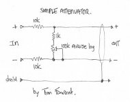
Attenuation
I'm looking to attenuate the input for the UcD 180 by 20 dB and I'd like to have a second opinion on either of these sollutions (or is possible to modify something on the board itself?)
#1: ~25k input impedance, ~1.5k output impedance, 'standard' H bridge attenuator ( http://beradio.com/notebook/passive_attenuators/ ), built as close as possible to the UcD's input.
Attachments
My twin beauties
HI All,
This is the first time I'll post something, but more is to come...
I had a little problem with the tools to get the plastic for the enclosure cut and formed to my liking, so I had to buy my own tools. (Router, bits, router table etc)
The result, I think, is quite pleasing, and will drive my Klipsch La Scala speakers happily for years to come.
Special thanks to Hypex, who very kindly sent me the SMD resistors for the input, which is connecting to a tube preamp.
I have also done some measurements: output at +/- 48 Volts rail is 110 Watts. THD @90Watts: 0.027%. Frequency response: within 0.3 dB over the audible spectrum, I'll post a photograph of the sweep later on (if anyone is interested).
Square Wave response at 1 Khz is exemplary, photo to follow.
Cheers, Arthur.
lucpes,
I don't think either of those are the best solution. Have a look at what Doug Self says http://www.dself.dsl.pipex.com/ampins/balanced/balanced.htm in particular secion 6 of Balanced Inputs.
I don't think either of those are the best solution. Have a look at what Doug Self says http://www.dself.dsl.pipex.com/ampins/balanced/balanced.htm in particular secion 6 of Balanced Inputs.
- Home
- Amplifiers
- Class D
- UCD180 questions