A crowbar doesn't make me think about the word "elegant"...
Besides, if fuses are not positioned between the power supply caps and the amplifier, to be blown by said crowbar, this means that the crowbar itself would have to thermally dissipate all of the energy contained into the supply caps and then some, until the mains fuse blows.
And, a charged 10.000 uF / 63V capacitor contains enough energy to turn a power mosfet into a mess of exploding bits of burning plastic and flames, unless you use some of these things salvaged from switchmode power supplies for train engines...
Me saw a TDA7294 vaporize and burst into about 10 cm high flames, just on the power from the caps, I had already cut the mains, but too late, at least it was spectacular.
I'd use a relay.
Protection?
I guess I am missing the point here, how does one use a fet to dump an AC signal? Would seem to me the bulk diode would object to that. I can see them used as a switch in the rail power line with one direction of current flow but this would necessitate a rather complex circuit for both the + and – switches. Also the fet would have to have a SOA far in excess of the output devices or it could end up part of the problem if things start to blow. All this makes a simple relay circuit look better and better.
Crowbar I think was from the rail road industry where they would use a real crowbar across the tracks to be sure there was no juice. Power supplies still have common usage of a crowbar circuit using a zener to detect over voltage and an SCR to dump the output. I guess something could be done with a triac but they are very slow.
Roger
You're right, I wasn't at all thinking when I said crowbar/fuse 🙂
Relay solutions aren't optimal either though. Contacts can weld, and can easily be a one time use situation.
This I find an interesting solution, and is more what I had in mind when I said to use mosfets:
http://www.geofex.com/Article_Folders/ampprot/dcprot.htm
Mosfets would handle that application with ease, and repeatedly. If I didn't have fuses already I'd seriously consider it.
Bgt said:
Cannot find the picture of your housing so I could see where it should fit best.
Picture illustrates how i can see k4700 should put in my amp.
Diode bridges should be moved between tranformers and put k4700:s in their old places.
Attachments

Pasi P said:
Picture illustrates how i can see k4700 should put in my amp.
Diode bridges should be moved between tranformers and put k4700:s in their old places.
Thats far away enough, you can also put them vertically and with the transformers to the front side of the cabinet and the rectifiers a bit to the left/right. These transformers on the Velleman kit are very small so they don't radiate humm as mutch as big ones.
Would the circuit in attachment work, what do you think?
I guess it's similar to what Hypex use, or at least what Bruno suggested in the UcD400 thread, except for the input resistors and caps (he mentioned 47k and 100 uF). The value for R5 should be calculated so that the resistance across the voltage drop from V(+) to 12V limits the current to same as 12V/internal resistance of the relay.
~Mikko
Attachments
mhelin said:Would the circuit in attachment work, what do you think?
I guess it's similar to what Hypex use, or at least what Bruno suggested in the UcD400 thread, except for the input resistors and caps (he mentioned 47k and 100 uF). The value for R5 should be calculated so that the resistance across the voltage drop from V(+) to 12V limits the current to same as 12V/internal resistance of the relay.
~Mikko
R5 supplied holding current can be a lot less than the pull in current. 75% should be a good number for all relays. R4 is to close to not working, not allowing enough voltage across T2 B/E to insure its being full on. This is more than a straight voltage divider as it also must supply current to the base. With only 22k to ground you need to raise R4 to 2 k and recalculate using the specs for T2 to insure that it supplies enough.
Roger
Ok, Any ideas which devices to use? BC550/560 for the first NPN and PNP, but which one would be good as T2? TIP32B?
Parts selection
I would be glad to help but need to know the specs of the relay you plan to use.
Roger
I would be glad to help but need to know the specs of the relay you plan to use.
Roger
Omron G2R-1E :
16A, 12V, rated current 43.6 mA, resistance 275 ohm
Another possible choice (better than Omron but difficult to source)
Zettler AZ725:
16A, 12V, coil resistance 260 ohm +/-10%
They are within 10% so something like 270 ohms would be ok?
16A, 12V, rated current 43.6 mA, resistance 275 ohm
Another possible choice (better than Omron but difficult to source)
Zettler AZ725:
16A, 12V, coil resistance 260 ohm +/-10%
They are within 10% so something like 270 ohms would be ok?
Recomended parts
The input cap is better served with a non-polar type of 1/2 the value, closest std. value = 22uf. Panasonic SU bi-polar = P1188-ND
I use and recommend Zetec transistors, the following are my recommendations;
NPN = ZTX692B-ND
@ 1amp current rating more than strong enough for pulling in the relay.
PNP = ZTX792A-ND
I also recommend a bidirectional overvoltage protector for going across the input cap;
P6KE15CADICT-ND this will stop any voltage over 15 volts.
These are all part numbers for Digikey and all are in stock.
http://us.digikey.com/
Roger
mhelin said:Omron G2R-1E :
16A, 12V, rated current 43.6 mA, resistance 275 ohm
Another possible choice (better than Omron but difficult to source)
Zettler AZ725:
16A, 12V, coil resistance 260 ohm +/-10%
They are within 10% so something like 270 ohms would be ok?
The input cap is better served with a non-polar type of 1/2 the value, closest std. value = 22uf. Panasonic SU bi-polar = P1188-ND
I use and recommend Zetec transistors, the following are my recommendations;
NPN = ZTX692B-ND
@ 1amp current rating more than strong enough for pulling in the relay.
PNP = ZTX792A-ND
I also recommend a bidirectional overvoltage protector for going across the input cap;
P6KE15CADICT-ND this will stop any voltage over 15 volts.
These are all part numbers for Digikey and all are in stock.
http://us.digikey.com/
Roger
mhelin said:Would the circuit in attachment work, what do you think?
I guess it's similar to what Hypex use, or at least what Bruno suggested in the UcD400 thread, except for the input resistors and caps (he mentioned 47k and 100 uF). The value for R5 should be calculated so that the resistance across the voltage drop from V(+) to 12V limits the current to same as 12V/internal resistance of the relay.
~Mikko
Mikko,
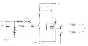
Your connection of the input NPN and PNP transistors for DC detection is very critical. The NPN side is OK, but the PNP is just acting as an emitter follower, without voltage gain, so it will only act reliably on very negative voltages. Better use something similar as in one of the Krell threads with two NPN transistors, one acting on positive voltages on its base, the other on negative voltages on its emitter. See figure from a KSA100 clone, but a multitude of circuits exists for this purpose.
Steven
Attachments
Steven said:
Mikko,
Your connection of the input NPN and PNP transistors for DC detection is very critical. The NPN side is OK, but the PNP is just acting as an emitter follower, without voltage gain, so it will only act reliably on very negative voltages. Better use something similar as in one of the Krell threads with two NPN transistors, one acting on positive voltages on its base, the other on negative voltages on its emitter. See figure from a KSA100 clone, but a multitude of circuits exists for this purpose.
Steven
Steven,
Yes a far more elegant circuit. The only thing I would be critical of is the very long time constants represented. Aside from that it is a better solution, symmetrical in its response, more sensitive and still not overly complex. The parts I speced would work well here to.
I did look at the other one a bit and figured the loss of gain in one direction was not critical as the relay driver has a whole bunch of gain, 300 minimum.
Roger
Thanks Steven and Roger!
The Krell circuit looks good, nice idea to use the emitter to bias the Q201 on negative voltages. However, the circuit works opposite way to the previous one, it pulls the relays after the startup timer (R203, C204), and in presence of DC it disconnect the speakers. Four parallel switches is nice (for speakers).
So about the time constants, C202 & C203 can propably be replaced with a non-polar 22uF + the TVS.
From Q201 and Q202 collectors to the relay driver PNP (from the previous circuit) is the 22k resistor OK, or should it be much smaller to give more base current and because of the reduced beta at low Vce (though it's 400 for the pnp driver at this current)? The Ib with 22k is just 0.5 mA and with beta of 400 the Ic would be about 200 mA (it still enough to pull the relay though). I would like to use 10k there, is it ok? Also the 2k resistor sinks some of this current (0.6V / 2k = 0.3 mA). How about connecting a 0.1 uF speedup cap across this resistor (22k or 10k or whatever you use)?
Also I can't find the ZTX692B (70V, 1A) from Farnell (Finland), closest are ZTX690B (45V, 2A Ic) and ZTX694B (120V, 0.5A Ic). The latter should be ok?
~Mikko
Noticed just that the G2R1E is a SPDT type relay so two is actually needed (so the load resistance will be ~135 ohms). Only DPDT type I could find is the G2R2S but it's rated only for 5A switched current (also the Zettler is a SPDT).
Consider putting their coils in series, I've seen it done somewhere, possibly on Doug Self's site.
Yeah I know you'd think so, but I don't think it's actually the case.
I've been looking for the site I saw that on for a little while now and will continue to do so until I find it to help you out.
If memory serves me (rare occurance) doubling source voltage isn't required as most relays are said to operate at even as low as 50% rated pull in, and then need even less after that.
I'll keep looking, my coffee isn't finished yet.
- Home
- Amplifiers
- Class D
- UCD180 questions