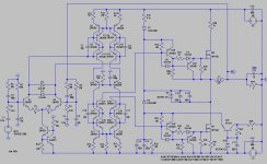
You already had when you shorted them out, like I said they're only for biasing the cascode transistor. For your input impedance just put a 10k to ground with the 1k in series. Though I'd recommend doing some additional work in order make it fully differential. You could also decouple the comparator from the HV rails.
I think you should set a realistic goal for the level of power you expect to get from it, and then add provisions for deadtime and maybe even buffers after the driver.
I think you should set a realistic goal for the level of power you expect to get from it, and then add provisions for deadtime and maybe even buffers after the driver.
classd4sure said:For your input impedance just put a 10k to ground with the 1k in series.
that would create severe DC offset issue at the output, because of the voltage drop over that resistor induced by the base current.
alternatively, one can use a pair of small signal mosfets - which is what I am going to try.
Far too minimalist to ever be "high end" I think.
I hope I can still say that without having to offer a complete alternative, but I have a tutorial to work on 😉
I hope I can still say that without having to offer a complete alternative, but I have a tutorial to work on 😉
I'd stick with your post #40 version without the added bias diodes.
Try to get it fully differential though, should make a big difference in the noise floor. Do you want full range high end sound or sub use only?
Try to get it fully differential though, should make a big difference in the noise floor. Do you want full range high end sound or sub use only?
I thought I would document the progress of this project via a blog. so here it is:
http://fokker00.blogspot.com/
http://fokker00.blogspot.com/
How the progress so far fokker?
Don't take out just cheap BJT if they are so important.... I think that some people see a class D project as simplest design contest... but I don't think so....
Don't take out just cheap BJT if they are so important.... I think that some people see a class D project as simplest design contest... but I don't think so....
not yet, katrino. I am still waiting for the arrival of those driver chips. sometime next week. I will keep you posted.
As to cheap transistors, I am working with a local shop here for custom made, high-end transistors. they came in gold plated casing, with 24K white gold leads, graphite PCB, four layered and gold-plated vias, titanium support, and 4-oz gold traces. in addition to diamond pads, and oxygen-free copper bars for cooling. the entire system will be suspened on a gyroscopically controlled and magnetic bearing balanced deck.
I hope it look high-end.
As to cheap transistors, I am working with a local shop here for custom made, high-end transistors. they came in gold plated casing, with 24K white gold leads, graphite PCB, four layered and gold-plated vias, titanium support, and 4-oz gold traces. in addition to diamond pads, and oxygen-free copper bars for cooling. the entire system will be suspened on a gyroscopically controlled and magnetic bearing balanced deck.
I think you'd rather put time and effort into designing a proper circuit than opting for exotic components, nothing beats a good design on a properly layed out PCB. Unfortunately Class-D done properly, hence with high-end aspirations, isn't something you whip up overnight, unfortunately and does not need exotic components to be honest.
Best regards,
Sander Sassen
http://www.hardwareanalysis.com
fokker said:not yet, katrino. I am still waiting for the arrival of those driver chips. sometime next week. I will keep you posted.
As to cheap transistors, I am working with a local shop here for custom made, high-end transistors. they came in gold plated casing, with 24K white gold leads, graphite PCB, four layered and gold-plated vias, titanium support, and 4-oz gold traces. in addition to diamond pads, and oxygen-free copper bars for cooling. the entire system will be suspened on a gyroscopically controlled and magnetic bearing balanced deck.
I hope it look high-end.
Go for diamond casing with built-in LEDs.
really? I thought this place is about not using "cheap transistors", and we don't really care about sound quality or electrical performance. we are all into exotic looks, not exotic sound.
maybe I should dial it back to silver casing rather than gold casing the 2n5551/5401 transistors? I pay about 1 cent each for those transistors and I thought gold casing them will make them worthy more of high-end Class D.
🙂
maybe I should dial it back to silver casing rather than gold casing the 2n5551/5401 transistors? I pay about 1 cent each for those transistors and I thought gold casing them will make them worthy more of high-end Class D.
🙂
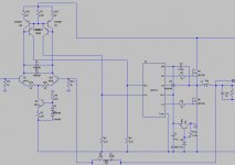
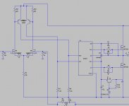
after starring at this so long, I was wondering if it would work, at least on paper, to use just a PNP comparator upfront and use the collector resistor voltage out to drive the gate drivers?
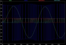
It is struggling in sim but I will let you know how it goes in real life: the first shipment of my gate drivers is in.
It is struggling in sim but I will let you know how it goes in real life: the first shipment of my gate drivers is in.
fokker said:after starring at this so long, I was wondering if it would work, at least on paper, to use just a PNP comparator upfront and use the collector resistor voltage out to drive the gate drivers?
It is struggling in sim but I will let you know how it goes in real life: the first shipment of my gate drivers is in.
You are some sort of turbo nutter freak!!!!!!!!!!
http://www.genomerics.org/fokker/simple.asc
Errrrrr, the feedback network (The one that Lars Clausen isn't allowed to use) is something that sorts out what the output filter does. (Like what everyone else uses but Lars Clausen can't)
The delay through the buffers affects the oscillating frequency.
And there is something about the ripple voltage at the output referred back to the input that plays around with things as well.
As your output voltage increases the slope of the opposite edge goes down so it takes longer for things to get back to the answer that they thought they were looking for in the first place and they kiss slower.
The frequency drops and the delay helps them move further apart before the next kiss.
It's a hysteretic convertor........ like what other people use but we are not allowed too.
Anyway.
BOOMSHANKA, now get back into the box before the Black Helicopters come around.
Oh, and thanks for that. It's really GOOD.
DNA
- Status
- Not open for further replies.
- Home
- Amplifiers
- Class D
- UcD / LTSpice help