Errr... Thanks for the offer, but I'm about to have a sandwich and I'll be really tired afterwards.
DNA
DNA
That's because it's heavier than your bottle and you're not used to that exertion without your mum helping.
Looking forward to seeing something original by you though, Mr. professional ....tutorial designer.
Looking forward to seeing something original by you though, Mr. professional ....tutorial designer.
Are we talk the same UcD diy?
But hi, turning the UcD? Are you sure? Because with using N-Fet (or you trying to use P-Fets?) you really make problems, lots of voltage supply level, very dificult level shifter hmmm...... I don't think it will better.....
anyway let see your result with real sound! not just stop quickly!
But hi, turning the UcD? Are you sure? Because with using N-Fet (or you trying to use P-Fets?) you really make problems, lots of voltage supply level, very dificult level shifter hmmm...... I don't think it will better.....
anyway let see your result with real sound! not just stop quickly!
Hi Kartino,
He just wants to use the discrete comparator, or some version of it, with your typical half bridge IC driver.
The usual discrete comparator uses npn's for sinking current from a pnp current source/high side switch, so the level shifting required is in built as part of the driver.
The gate driver IC doesnt' have that, so by inverting the comparator you get the opposite effect, with a few trade offs in the input stage, probably not a very big deal.
The output stage will of course remain dual N - channels, and the IC driver can be made to work at higher voltages easier than the discrete ones can.
As he said, it'll save him additional supplies which is the main benefit to using this as opposed to your usual comparator, it's not a bad option.
DNA, I resent your remarks about how I made the circuit by poking around a UCD. My ethics prevent that, and it's been a transparent process of learning for me. However I don't mind learning from such a fine example, and don't pretend to know more than I do. I was obviously correct in my reply when I said it was being complicated for nothing, but no I didn't have a ready solution, it's the kind of thing I work on.
Maybe it's time we saw something from you other than your struggle with tutorials and your whinning about the patent of someone who's a better designer than you could hope to be, without even understanding it. From the looks of your website though, it looks like you've already given up on the audio aspect to concentrate on the smps' you already know, or pretend to. There's already been a number of people on here who've built my rubbish or variations on it and they all seem happier for it. How many built your rubbish? Oh yeah, it couldn't be patented because there's no way it could have worked. Wot a knob.
Chris
chris, you are correct, as usual.
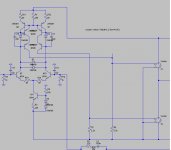
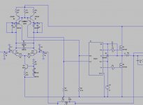
question tho, on my last schematic where the comparator is inverted, what does those two diodes D12/D13 and Q3/Q6 do?
I took out Q3/Q6 and it worked as well. so why do you have them?
Also, has anyone successfully simulated this in OrCad? I couldn't get it going and it looks like a start-up / initial condition issue.
Hi,
In this case you probably don't need them or the diodes.
The reason they're there is because with the disrete drivers there's more dv/dt for the high side than for the low side driver, since they each level shift to very different potentials, which can lead to a few problems.
So using a cascode transistor for the high side helped guard against the increased dissipation, using one for the low side keeps all things equal (delays), and the diodes are a minimal component count way of keeping the cascode transistor biased. You could use two or three or an LED as well, but I found one was fine.
In this case you're having them both switch to the same potential with the same dv/dt so it shouldn't be much of a problem as long as you have fast enough transistors for a nice clean and fast switch. At higher rail voltages they may be of some use again though.
Most of my work for it was done with orcad, of course I haven't tried this circuit exactly.. if you post it I'll be happy to help you figure it out though. Upping the transient itteration limite in simulation options is often useful. What's the error?
chris, it is no error but the circuit just isn't oscillating. one of the switches stays open after a few u-seconds.
I will post the schematic later. thanks.
I will post the schematic later. thanks.
Are you sure the outputs of the comparator are in proper "phase" with the output stage for feedback to work?
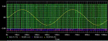
yes. the interesting thing is that the LTSpice version works just fine but the OrCad version (which is identical) would not oscillate. thus my puzzle.
Hi,
I threw together a sim in pspice based on this, with ideal voltage controlled switches. It's working extremely well and required nothing special.
One thing you may not be aware of is that the ideal switches can use some editing. In properties I changed Roff=1e10 instead of 1e6, Ron=.005 instead of 1, and there's two thresholds, I left Von=1 and changed Voff to 0.5 instead of 0.
Attachments
Look at your switch parameters, doesnt' seem to make sense to have both Vthresh and Vhigh. I have Vlow and Vhigh, there is no Vt.
I dumped the old S_ST switches and used the S switches which has Von and Voff. Now it is working.
It may have something to do with the S_ST switch models in OrCad.
It behavies just like the same model in LTSpice.
Thanks.
It may have something to do with the S_ST switch models in OrCad.
It behavies just like the same model in LTSpice.
Thanks.
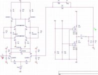
I also took out the two casecoding transistors and shorted the two diodes. no impact I can see of. so I am going with the simpler schematic.
What this proves to me is that this concept seems to work. I will just need to work it out in the real world to see how true the simulation is.
Now, two more questions:
a) how to increase the gain? the 22k resistor seems to control the gain, but only to certain extent as the C/R in parallel with it becomes dominant.
b) how to increase the input impedance. if I can increase those 1k resistors on the bases to like 22k or even 10k, I would be happy.
Does anyone of the formula for the oscillating frequencies and gain for this amp? Thanks in advance.
Hi,
Because your circuit similar to quasi, I think that you can not use same voltage VCC level for your driver and your high side FET. Your driver VCC shall over that FET VCC.
Beside that you still simulate with ideal switch. Try with mosfet symbol...
waiting the progress...
Because your circuit similar to quasi, I think that you can not use same voltage VCC level for your driver and your high side FET. Your driver VCC shall over that FET VCC.
Beside that you still simulate with ideal switch. Try with mosfet symbol...
waiting the progress...
Hi Kartino,
That's just the comparator working with an ideal output stage setup in such a way that it can accept a gate driver IC. The next step is to include the IC, and that will take care of the bootstrap supply. Should be fine.
REgards,
Chris
That's just the comparator working with an ideal output stage setup in such a way that it can accept a gate driver IC. The next step is to include the IC, and that will take care of the bootstrap supply. Should be fine.
REgards,
Chris
- Status
- Not open for further replies.
- Home
- Amplifiers
- Class D
- UcD / LTSpice help