bingo!
fucgger is alive! but not well, 🙁.
I struggled a bit to get the simple version to work. However, my test environment is a +/- 7v 2a power supply and I used a 10ohm current limiting resistor so there is too much supply ripple caused by the CL resistor. so I switched out to use a current mirror as the load, which made the circuit almost identical to the Phillips application note.
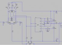
Here is what I have, except that I am running off a NCP5181 as the driver chip.
I had this thing wired on a breadboard (yes, breadboard!) for two weeks and couldn't get any output out of it - my "signal generator" is a HK630, line-out to a 10:1 step down audio transformer (so I don't accidentally fry my HK), then into my fucgger. the test load is a speaker.
no sound whatsoever. I went over the simulation, the breadboard, pulled out component to test and built this thing three times. no go.
then I thought maybe the audio transformer was fried so I unplugged it, with the fucgger powered on, and I heard a/c hum!
I realized at that moment my problem was with my signal source. so I retraced everything and found out that I had the rca plug on "line-in" on the HK! switched it over to line out and this sucker started to sing! with two 10ohm CL resistors hooked to it!
It does have severe distortion: to be expected as I used a 470ohm resistor on the current mirror's base - extra-long dead time. I will upload the picture when I get some time.
and I will start fine tuning it later on. But I am happy that fucgger is finally alive (or it has been alive for quite sometime now but I just didn't know).
tons of thanks to chris and genomerics.
fucgger proved, once again, that this type of circuits works.
parts that I don't in the actual circuit are: R19, R20, R6/D2, R5/D1.
fucgger is alive! but not well, 🙁.
I struggled a bit to get the simple version to work. However, my test environment is a +/- 7v 2a power supply and I used a 10ohm current limiting resistor so there is too much supply ripple caused by the CL resistor. so I switched out to use a current mirror as the load, which made the circuit almost identical to the Phillips application note.
Here is what I have, except that I am running off a NCP5181 as the driver chip.
I had this thing wired on a breadboard (yes, breadboard!) for two weeks and couldn't get any output out of it - my "signal generator" is a HK630, line-out to a 10:1 step down audio transformer (so I don't accidentally fry my HK), then into my fucgger. the test load is a speaker.
no sound whatsoever. I went over the simulation, the breadboard, pulled out component to test and built this thing three times. no go.
then I thought maybe the audio transformer was fried so I unplugged it, with the fucgger powered on, and I heard a/c hum!
I realized at that moment my problem was with my signal source. so I retraced everything and found out that I had the rca plug on "line-in" on the HK! switched it over to line out and this sucker started to sing! with two 10ohm CL resistors hooked to it!
It does have severe distortion: to be expected as I used a 470ohm resistor on the current mirror's base - extra-long dead time. I will upload the picture when I get some time.
and I will start fine tuning it later on. But I am happy that fucgger is finally alive (or it has been alive for quite sometime now but I just didn't know).
tons of thanks to chris and genomerics.
fucgger proved, once again, that this type of circuits works.
parts that I don't in the actual circuit are: R19, R20, R6/D2, R5/D1.
Attachments
did more digging last night.
the voltage drop over the 10ohm current limiting resistors is about 4.6v at idle. given a peak current about 1a, vs. 1.2a predicted by the simulation.
so the amp is essentially working on +/- 3v! no wonder the sound sucks big time.
I will try to run it at higher voltage today.
BTW, it has no turn-on/off pops, and DC offset is at 6mv, without any matching of the transistors and emitter regen resistors.
Well, at least the current was limited by them as well for the initial test phase, maybe saved a fet or two eh?
That's far too huge for a current sense though, 10mohm or less sound good?
Keep us posted.
That's far too huge for a current sense though, 10mohm or less sound good?
Keep us posted.
More update: after lowering the current limiting resistor to 1ohm, I burned quite a few ncp5181, only to find out for whatever reason, the supply voltage would surge to 25vdc before settling down to 14vdc. and the ncp couldn't survive such a surge.
dropped in the ir2011 (which has almost idential pin-out, except it is oriented 180-degrees from the NCP), the sound quality improved considerably.
However, the mosfets ran very hot very quickly, with average idle current in the 1amp range - I guess there is some overshoot.
Will investigate it further.
If mosfets in your schematic are the same you're using, they're not the easiest to drive or most efficient. Add some followers to the drivers and/or get a better fet.
I think you're on the right track and you probably don't absolutely need to do as recommended above, but it sure won't hurt.
I think you're on the right track and you probably don't absolutely need to do as recommended above, but it sure won't hurt.
thanks, chris. I will try that out as well.
More update: because of the larger CL resistors, I added two 220u capacitors post the CL resistors to help stabilize rail voltages. Sound quality improved further.
With my +/- 7vdc issue supply and 20ohm CL resistors, this thing sounds pretty loud, at about 1w or so, if I may estimate.
It now has almost zero DC offset, with no transistor matching and no Re.
My next assignment is to move it to a +/- 32vdc supply and see how it performs.
it is now running at +/- 32vdc. Sound quality is slightly improved and it can be made significantly louder.
Problems still remain:
a) heavy distortion: kind of like cross-over distortion in a typical Class C amp. I am using a 470ohm resistor for dead time control on the comparator.
b) hissing: I am not sure if this is cased by the CL resistors or something else in the amp.
it ran very cool, without any need to cool the two output devices.
In that case, hissing is expected, you can scratch it off your list. Although shoot through/ringing /overheating can all go hand in hand too.
I am the front end is pretty well done. I am still playing with the driver stage so I am going to make a two-piece amp, with the front end on a protoboard and the driver / mosfets on a breadboard.
I am also going to replace the tail resistor with a CCS just to simply things a little -> this will make the front end almost identical to the Phillips application note.
Let's see how this round goes. Thanks and it has been quite entertaining.
I am also going to replace the tail resistor with a CCS just to simply things a little -> this will make the front end almost identical to the Phillips application note.
Let's see how this round goes. Thanks and it has been quite entertaining.
i separated the two - on another breadboard - and now hissing is gone and the amp is dead quiet at idling.
now, I just need to figure out the distortion.
now, I just need to figure out the distortion.
it has been about 12 hours for fucgger to run at +/- 32vdc into a 4-ohm load (2x 8ohm resistors), at a gain of 33x. The mosfets are still at room temperature.
It is dead quiet at idle but when fed with a signal, it isn't exactly mid-fi, yet. there seems have several "cross-over distortion" which likely is dead-time related. I will work it out in the coming weeks.
three driver ICs were used, LM5104 (through an adapter, best sound quality), ir2011 (medium quality) and NCP5181 (lowest sound quality).
I think the experiment shows that the basic schematic is sound, and also it needs a lot of refinement - which is probably something Hypex brings to the table and what you pay for for their UcD modules.
one thing I forgot to mention: this thing is a radio station!
whenever it is powered on, there is always this hissing in my HK630 which is also on the bench but about 1 meter away from the fucgger.
one thing I learned is that breadboarding really isn't a practical idea for Class D. It is fine to prove a viable concept but for anything more serious, you will have to get it done through a good layout.
more update: I may have found the source of the distortion - the amp reproduces the negative side of the cycle perfectly. However, it would NOT produce anything on the positive cycle. Swapping the mosfets doesn't help, nor does swapping the driver IC. Input to both the High side and Low side pins is correct.
I am suspecting that the bootstrap circuit is to blame. I am using a 0.47u 250v film cap and a 1n4148 signal diode there. I will swap out the signal diode first and then go from there.
I am suspecting that the bootstrap circuit is to blame. I am using a 0.47u 250v film cap and a 1n4148 signal diode there. I will swap out the signal diode first and then go from there.
Why swap what you can so easily test?
That cap is way small.
You need some means of pre charge+delay before enabling the output too if you don't have it already.
That cap is way small.
You need some means of pre charge+delay before enabling the output too if you don't have it already.
Did you try your calculation with say a 20Hz sine wave clipped 20%?
I can't recall what others found to work OK with IC drivers, I'm sure they'll chime in. Maybe try a few uF, electrolytic is OK.
I can't recall what others found to work OK with IC drivers, I'm sure they'll chime in. Maybe try a few uF, electrolytic is OK.
the cap doesn't see the audio signal: it only sees a 300khz+ pwm signal.
nontheness I will try a larger cap. Thanks.
I thought maybe the high forward voltage drop on the 1n4148 is to blame but on the other hand I have seen people using them successfully in this type of applications and actually in some application notes as well.
nontheness I will try a larger cap. Thanks.
I thought maybe the high forward voltage drop on the 1n4148 is to blame but on the other hand I have seen people using them successfully in this type of applications and actually in some application notes as well.
- Status
- Not open for further replies.
- Home
- Amplifiers
- Class D
- UcD / LTSpice help