so is the amplifier complete ?
we need pictures ...
regards,
savu
Same question. Please post waveform when it is completed.
Cheers,
The parts I had ordered (MOSFET, b'strap diode and choke core) have not yet arrived.
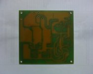
My PCB has been fabricated and has arrived. Pls see picture. Also, I have bought some parts (ICs etc) .That is all as of now.
Will post everything as soon as I finish building.
Anything else I have would be the subwoofer and its box.....
Would you like to see pictures of the woofer? Anyway I shall post those at the end (of everything).
Attachments

Last edited:
why oh why didn't you use the the other layer of the board for a ground plane ?
the difference would have been incredible.
regards,
savu
the difference would have been incredible.
regards,
savu
Hi savu,
It is a single-sided TH board. I shall be trying SMD sometime later. I will be having a completely metallic cabinet which will be grounded and the board screwed to it without much gap.
It is a single-sided TH board. I shall be trying SMD sometime later. I will be having a completely metallic cabinet which will be grounded and the board screwed to it without much gap.
So is it going to be that bad?Doesnt the metallic cabinet (only few mm from the board), act like a good ground plane?
Last edited:
Hopefully it is not going to be that bad...
but for the next project take this in consideration also.
regards,
savu
but for the next project take this in consideration also.
regards,
savu
Received the components (MOSFETs), diodes and 23 mm f'cube toroid (4c65).
Will begin building soon.......
Will begin building soon.......
Hi Friends,
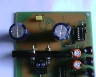
I have completed building my amplifier (but for the choke).
Please see the pictures.
I ve a capacitor that says 105K........Is it 1uF ? rating is 250V (got it from the front end of an smps)
Can I put it across +/- rails like the x capacitor in an EMI filter?
I have completed building my amplifier (but for the choke).
Please see the pictures.
I ve a capacitor that says 105K........Is it 1uF ? rating is 250V (got it from the front end of an smps)
Can I put it across +/- rails like the x capacitor in an EMI filter?
Attachments

Last edited:
I have the core TN 23/14/7 - 4c65 (Al=87)
16 t = 22uH
17 t = 25uH
18 t = 28uH
But what wire gauge should I use? Pls help. I ve everything expect the inductor.
16 t = 22uH
17 t = 25uH
18 t = 28uH
But what wire gauge should I use? Pls help. I ve everything expect the inductor.
Hi friends please tell me whether I can use SWG 14 (2.1mm dia) for the choke ?
What should be my window utilisation factor ? Is there any problem if I use near 100%?
What should be my window utilisation factor ? Is there any problem if I use near 100%?
Hi friends please tell me whether I can use SWG 14 (2.1mm dia) for the choke ?
What should be my window utilisation factor ? Is there any problem if I use near 100%?
Calculate the circumference of inner side of toroid and then see whether you can use 2.1mm wire or not.
Allow a gap of 3-5mm between start and end of the winding to decrease capacitive coupling between switching node and speaker output.
The inner circumference is PI*inner diameter = 3.14159*13.1 = 41.15mm
2.1 mm dia wire will make exactly 41.15/2.1 = 19 turns.
But the window utilisation is almost 100% which i dont think is a correct value to use.
That is why I posted the question.
The radius of wire maybe subtracted from inner dia so that the net inner dia is 12mm. So its exactly 18 turns.
But, the same question, again.
If I reduce the dia to 1 mm (19SWG) maybe the WUF will be near 50%. 🙂
Last edited:
The inner circumference is PI*inner diameter = 3.14159*13.1 = 41.15mm
2.1 mm dia wire will make exactly 41.15/2.1 = 19 turns.
But the window utilisation is almost 100% which i dont think is a correct value to use.
That is why I posted the question.
17 Turns + 4mm gap between start-end is right option for you😉
So thats 19SWG (1mm dia). Isnt it?
Thanks.
The DCR will be 21.3 ohms / km * 2(10.6+7.5) /1000 * 17 = 13 mOhms. 🙂
Thanks.
The DCR will be 21.3 ohms / km * 2(10.6+7.5) /1000 * 17 = 13 mOhms. 🙂
Last edited:
So thats 19SWG (1mm dia). Isnt it?
Thanks.
why not 17turns of 2.1mm SWG14?
- Status
- Not open for further replies.
- Home
- Amplifiers
- Class D
- Ucd for s/woofer appln