..... These circuits won't achieve higher THD by oscillating at either higher or lower frequencies .....
You men lower, right? 240 kHz is the optimum ....
Now im using IR2010 which have shorter delays than the IR2110 but atleast it would give a clue, just need to familiarize myself with ltspice, downloading the latest version atm.
Eva, what you write makes perfect sense ....
Make the circuit as fast as possible (propagation delay as little as possible), choosing fast comperators, fast level shifter, low propagaton driver and fast MosFets ... and choose an optimal switching freq. ....... but I'll have to do some more sims to determine what exactly the optimal freq is as I guess it changes with duty cycle (level out) ... at least the compromise betwen odd and even order harmonics ....
.... If not making UcD and therefore usnig an integrator in the input, what makes for the perfect opamp I wonder?
You men lower, right? 240 kHz is the optimum ....
Yes, I meant lower THD 😀
Crap! Theres no LM311 in ltspice 🙁
Hello Tekko
Attached you can find the model
Regards,
savu
Attachments
Eva, what you write makes perfect sense ....
Make the circuit as fast as possible (propagation delay as little as possible), choosing fast comperators, fast level shifter, low propagaton driver and fast MosFets ... and choose an optimal switching freq. ....... but I'll have to do some more sims to determine what exactly the optimal freq is as I guess it changes with duty cycle (level out) ... at least the compromise betwen odd and even order harmonics ....
.... If not making UcD and therefore usnig an integrator in the input, what makes for the perfect opamp I wonder?
hello baldin,
A simple exercise of imagination.
You take a class d amp.
Input stage to output stage there are these components:
LT1711 - 4.5nS delay
HCPL-9000 - 12nS delay
TC4420 - 55nS delay (thinking of using very fast zetex transistors for better results)
IRFH5020 - 21nS delay
This is a total of 92.5nS propagation delay.
You will have a huge dv/dt.
Regards,
Savu

Tekko: rast working 🙂
Savu .... not sure I get your point ... are you refering to my question on opamp choice?
Savu .... not sure I get your point ... are you refering to my question on opamp choice?
Ok ...
My simulations shows I'll have some 225 nS of delay .... think I have some 300 nS in my current amp ...
My simulations shows I'll have some 225 nS of delay .... think I have some 300 nS in my current amp ...
Confirmation of the original version's idle freq limitations 🙂
I received the original version of this amp from a friend on the forum.
it was running at 120Khz.after a lot of tweaking the component values (still don't know how to calculate feedback loops), i have made it go up to 225Khz, but that's the most that it does.
tomorrow i will try to modify the dead time, maby i'll get to 300khz.
but for now 225Khz is as far as it gets.
this is because of the lm311 wiring.
imho tekko's version is far superior.
regards,
savu
Ok ...
My simulations shows I'll have some 225 nS of delay .... think I have some 300 nS in my current amp ...
But if one manages to get under 100nS that would be great.
It should have great dynamics. the layout would be a problem. you have to use all smd to get this.
regards,
savu
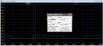
According to simulation i have around 18nS delay from comparator output to amp output.
... seems a bit strange as IR2110 is specified at around 120nS .... here is a sim from High input of the IR2110 to High output .......
Ans a sim from LevelShift in to LevelShift out
But maybe you are not talking about IR2110 ..... ??
Attachments
Last edited:
Ahhh so IR2010 has less than 18nS propagation delay ..... will have to look at that datasheet again ......
.... you can find/show the propagation delay of the whole amp by applying a large enough signal to the input so that it starts clipping, then the shortest pulses on the output (before the filter) will be 2 times the propagation delay ....
.... you can find/show the propagation delay of the whole amp by applying a large enough signal to the input so that it starts clipping, then the shortest pulses on the output (before the filter) will be 2 times the propagation delay ....
In real world, IR2110 with 5V logic supply and 12V gate supply, and at a temperature around 45ºC, will exhibit internal delays around 200ns. The delay figures given on datasheet tables are for 15V logic and 15V gate supplies, which results in shorter delays.
It all started because I was experiencing an overall propagation delay 30% higher than expected (by adding datasheet figures for all components in the signal path), so I decided to measure the actual propagation delays.
Sometimes datasheets from International Rectifier, ST and others reflect too optimistic working conditions on purpose, to obtain more attractive ratings and win on quick comparisons. Lesson to learn: Take some time to read all notes (even if they are put several pages away on purpose) and fine prints.
Same applies to IR2010, good but a bit slow.
Last edited:
I use 15V for the IR2010, both on logic and power side.
Btw where is the button for cursors ? I cant find it in ltspice.
Btw where is the button for cursors ? I cant find it in ltspice.
Last edited:
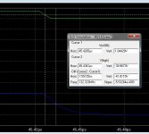
..... wonder how you got the 18nS if you didn't find the cursor 😉
.... Anyway you just mouse click on the "legends" or signal names above trace window ... if you right click you get an option on useing either no. 1 or 2 or both for the choosen signal ....
.... Anyway you just mouse click on the "legends" or signal names above trace window ... if you right click you get an option on useing either no. 1 or 2 or both for the choosen signal ....
Attachments
- Home
- Amplifiers
- Class D
- UCD 25 watts to 1200 watts using 2 mosfets