HI Stewin
greetings 80 volts dc +/- used with IRFP260N
warm regards
andrew
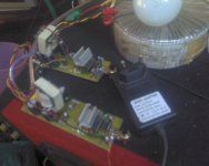
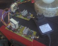
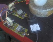
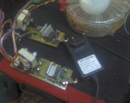
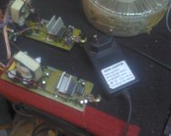
in my irs900d the ir2110 ic heats up , until i have placed a heatsink on top of the ic with superglue.
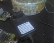
i have two channels and i am using one adapter of 12vlts to serve both channels .
but i have no noise issues and the amp is clear . the main voltage is +/-45vlts gate resistors are 100ohms output fets are irfp250n they are cool even though i have not mounted them on a heat sink. when i push the amp real hard at that voltage the outputs only warm up a little.
i will juice it up to +/- 80vlts
Attachments
-
 Pic_1212_008.jpg200.7 KB · Views: 1,765
 -
 Pic_1212_009.jpg200 KB · Views: 1,641
 -
 Pic_1212_010.jpg205.7 KB · Views: 1,470
 -
 Pic_1212_011.jpg200.3 KB · Views: 1,336
 -
 Pic_1212_012.jpg198.3 KB · Views: 1,232
 -
 Pic_1212_013.jpg182.5 KB · Views: 286
 -
top lay(1).pdf196 KB · Views: 810
-
 ucd 25 watts to 1200 watts using 2 mosfets pg 218 ab722e449ca921e4.jpg263.3 KB · Views: 905
Hi Hadi,
mistake:
do not use Lm7812 for TTL ics (74HC04) it is LM7806 or LM7805 otherwise it will damage. re check IC damaged or not.
how much turns for T106-2?? picture shows @ 80 Turns is it? you can reduced to 59 turns.
connected power supply not mentioned(no picture)
Regards
MANOJ
mistake:
do not use Lm7812 for TTL ics (74HC04) it is LM7806 or LM7805 otherwise it will damage. re check IC damaged or not.
how much turns for T106-2?? picture shows @ 80 Turns is it? you can reduced to 59 turns.
connected power supply not mentioned(no picture)
Regards
MANOJ
Hi sir manoj
yes 80 turn
i have resistors 820 ohm and 680 ohm with 1% telorance for changhe the FREQ
i use LM7806 like your shematic in board
i whant use LM7812 for bias section not in the board
amp is alive and TTL IC is work good
how can i change the curent option on your board?
yes 80 turn
i have resistors 820 ohm and 680 ohm with 1% telorance for changhe the FREQ
i use LM7806 like your shematic in board
i whant use LM7812 for bias section not in the board
amp is alive and TTL IC is work good
how can i change the curent option on your board?
how can i change the curent option on your board?
Hi Hadi,
i will send the schematic
regards
Manoj
stewin what is your inductor value?
20turns in the ee core from pc power supply with 3mm gap in the center
thanks to sir manoj
some thing wrong in this pdf file😕
the colector of 2n5551 must be connect to leg 2 off ne555 ic not leg 5 !!!!
correct ?
thanks sir manojHi Hadi,
Over current (I) = 550mv/0.04 Ohm x 1k5+1k/1k = 34A😉😉
remove resistor R2 and R4(1K) OC will be @13A
Regards
Manoj
some thing wrong in this pdf file😕
the colector of 2n5551 must be connect to leg 2 off ne555 ic not leg 5 !!!!
correct ?
sir manoj
in your over current protection pdf file you write from filter.
which filter you mean ?
amp out put filter or your power board big capasitors and diod brighe filter?
and
can you please share a beter form of your formula for over current section like this over current(I) = V .../ R... * R1 + R4 / R2
or some thing like this ?
thanks
some thing wrong in this pdf file
the colector of 2n5551 must be connect to leg 2 off ne555 ic not leg 5 !!!!
correct ?
Hi Hadi,
schematic shows over current section only.not "leg 5 of 555 ic " it is BIAS center pin "s".
Over current (I) = 550mv/0.04 Ohm x 1k5+1k/1k = 34A
550mV= Transistor ON min voltage(V)
0.1R*3= 0.04 Ohm--- Current resistor(R)
R1=R3 --- 1K5
R2 & R4= 1K
I = V/R x R1+R2/R2
which filter you mean ?
amp out put filter or your power board big capasitors and diod brighe filter?
Yes Power Board Bridge diode and Big Capacitor filter.
Regards
MANOJ
thanks to sir manoj
i am confusing with this formula 😕
Hi Hadi,
550mV= Transistor ON min voltage(V)
0.1R*3= 0.04 Ohm--- Current resistor(R)
R1=R3 --- 1K5
R2 & R4= 1K
I = V/R x R1+R2/R2
Regards
MANOJ
i am confusing with this formula 😕
i am confusing with this formula
Hi Hadi,
Confuse what???
I=V/R is normal
when you use series and shunt resistor for transistor
I=V/R*R1+R2/R2 If you are not using R2
take I=V/R only( R1 not more than 2K5)
Regards
Manoj
Hi All,
I would like to delete all my attachments more than 30 days.
It will keep only for a month
andrew pls accept this.
MODERATOR : you can delete my 30days old attachments.
Regards
MANOJ
I would like to delete all my attachments more than 30 days.
It will keep only for a month
andrew pls accept this.
MODERATOR : you can delete my 30days old attachments.
Regards
MANOJ
Hi Hadi,
My new AUD600 with pre and post feedback, advantage the tight mid freq. is soft now.the Low, mid and High is perfect.
Regards
MANOJ
My new AUD600 with pre and post feedback, advantage the tight mid freq. is soft now.the Low, mid and High is perfect.
Regards
MANOJ
Hi Hadi,
My new AUD600 with pre and post feedback, advantage the tight mid freq. is soft now.the Low, mid and High is perfect.
Regards
MANOJ
Wow great. Will you post it's design. Really want to build one
Thanks
thanks to sir manoj
you steal use ETD29 ?
please share that with me
Hadi.ghr.e.61@live.com
thanks
have a nice day dear🙂
Hi sir manojHi Hadi,
My new AUD600 with pre and post feedback, advantage the tight mid freq. is soft now.the Low, mid and High is perfect.
Regards
MANOJ
you steal use ETD29 ?
please share that with me
Hadi.ghr.e.61@live.com
thanks
have a nice day dear🙂
Hi sir manoj
you steal use ETD29 ?
please share that with me
Hi Hadi,
yes ETD29 . it can go up to 500KHz no problem.but i am using 250KHz only.after testing i will send to you.
Regards
MANOJ
- Home
- Amplifiers
- Class D
- UCD 25 watts to 1200 watts using 2 mosfets