thanks for the feedback....i just wrote it to get some attention...actually i dint mean that...i know all the designs are working....but i'm having a small prob and nobody hear has given me a correct solution yet....what can this thing make to give out square wave output after coil...and on applicaton of signal generator with 1khz it gives out 3khz....any idea can u suggest!!!!!!!!!🙄🙄🙄Hi Sweetperfume
greetings have PATIENCE i started this thread i took me a year to get the ucd amp working 30 IR2110 ics smoked out but the experience taught me something check everything carefully components shorts on pcb diodes you use dont PANIC all the designs are working i have tested them all
warm regards
andrew lebon
what can this thing make to give out square wave output after coil...and on applicaton of signal generator with 1khz it gives out 3khz....any idea can u suggest!!!!!!!!!
Hi sweet,
what coil you are using now and what is your switching frequency,MOSFET Used,supply voltage ......
regards
MANOJ
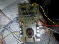
i had used 33uh coil... switching freq is very low at around 200khz...unable to set it...mosfet are irf250N ant supply voltage is +/-35 volts..Hi sweet,
what coil you are using now and what is your switching frequency,MOSFET Used,supply voltage ......
regards
MANOJ
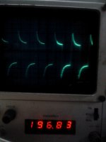
when the the 1nf capacitor is removed...the output is very clear when applied player but not when signal generator is connected....1st image shows freq with input frm signal generator...its self oscillating freq wave before inductor...
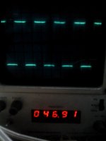
2nd after applied signal of 1khz
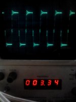
3rd after coil with signal generator
Attachments
Last edited:
take a look at the waveforms which i got and freq..i dont think its correcttry using IRF540N they are 100V fets and are much more faster than irfp250n
sweetperfume:
You said that you have sware wave output. Are you sure you are not clipping the output?Decrease input signal to 1/10 and see what happens.
You said that you have sware wave output. Are you sure you are not clipping the output?Decrease input signal to 1/10 and see what happens.
the thing remains the same...the third image shows the freq after the inductor coil....it is square wave take a look at it...i lowered the signal but onle waveform size reduces not its paternsweetperfume:
You said that you have sware wave output. Are you sure you are not clipping the output?Decrease input signal to 1/10 and see what happens.
what does that mean????????/I can not identify the problem without first hand on your amplifier to measure it.🙁
It means i can not identify the problem remotely, but i will try a little more.
Measure signal at comparator pins IN+ and IN- and post it.
Measure signal at comparator pins IN+ and IN- and post it.
this if the frequency on -IN but it shows unstable freq of 140khz and aroundIt means i can not identify the problem remotely, but i will try a little more.
Measure signal at comparator pins IN+ and IN- and post it.
this if the frequency on -IN but it shows unstable freq of 140khz and around
Attachments

Hi Nano
greetings 220K 1 watt resitor burn in smps while power on any hint whats wrong
warm regards
andrew lebon
greetings 220K 1 watt resitor burn in smps while power on any hint whats wrong
warm regards
andrew lebon
the smps works perfect no errors have several mounted.Hi Nano
greetings 220K 1 watt resitor burn in smps while power on any hint whats wrong
warm regards
andrew lebon
hello Sweet as what you have shown on the first image that situation is when your both output transistor are beyond or very low from it's pinch-off voltage or threshold,try to check the threshold voltage of the power mosfet you're using,(gate source voltage)IR's hi & lo output is between 4 to 5v to drive the output transistor,hope this will help,good day.
- Home
- Amplifiers
- Class D
- UCD 25 watts to 1200 watts using 2 mosfets