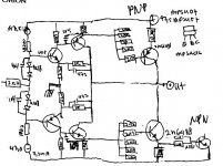
syn08 said:Yes and it works pretty well for EF output stages.
For CFP, it's more complicated.
Here's a possible solution that I am looking into, for a MOSFET CFP stage (take this as a concept only).
Note the bipolar drivers that can both source and sink current
from the MOSFET gates.
thanks for your schematic example, syn08
I will study a bit more on this cross-conduction issue.
May come useful in some of my future simulation amplifier.

🙂 nice idea Stee
you have great ideas
Passive voltage amplifier stage!!!
using one up-transformation
hehe 😀 will put some headache & questions into some heads here
Lineup
you have great ideas
Passive voltage amplifier stage!!!
using one up-transformation
hehe 😀 will put some headache & questions into some heads here
Lineup

Hello,
I'm sorry but what is innovative with that "UAS" design since it's just a conventionnal CFP? What is new? For the GAS, I don't really get the idea : the Vbe is quite unpredictable with bipolars and this one would require some good matching to be ok when idling. And what is the presumed advantage of this rather complicated topology? Any explaination?
I'm sorry but what is innovative with that "UAS" design since it's just a conventionnal CFP? What is new? For the GAS, I don't really get the idea : the Vbe is quite unpredictable with bipolars and this one would require some good matching to be ok when idling. And what is the presumed advantage of this rather complicated topology? Any explaination?
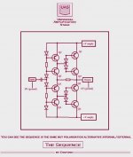
Made me think about.... this was the advantage to me
reflections about... was nice to read his brainstorm.
I have accepted Stee invitation to dream with him.... so... i have joined him in this trip... was good to follow his sequence.
Molto benne fratello.
Carlos
reflections about... was nice to read his brainstorm.
I have accepted Stee invitation to dream with him.... so... i have joined him in this trip... was good to follow his sequence.
Molto benne fratello.
Carlos
C & B Complementary and Balanced
thank you very much for your attention
the continuation of this thought around the problem of VSA
( the true footprint of each amplifier )
deviates now in two roads (as happens in every novel)
Research has as its basic criterion as C & B Complementary and Balanced
UAS become an amplifier with passive VSA ... perhaps with Tamura and Mosfets
GAS represents a new sound card that promises emotions from Class A
the new architecture should allow a very harmonious timbre without wasting power (AB Bias)
but at the moment need a test of listening 🙄
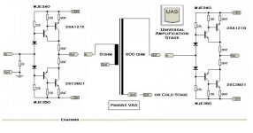
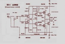
UAS progress
hello to all
the progress of UAS is this:
transformer have sound of transformer...
better idling VAS with accurate transistor like 2SA1360 and 2SC3423 special for Audio Frequency Amplifier Applications in my SONY
but need a little load...
Collector current IC -->50 mA
so need a mosfet
mosfet can't drive loudspeakers with the "round" sound of bipolar
see the solution
will testing in few days
Attachments
if you like to see base of recent test
http://www.esafono.it/sonytest.jpg
Darian: I don't know, it's just research to found better sound...
http://www.esafono.it/sonytest.jpg
Darian: I don't know, it's just research to found better sound...

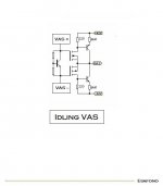
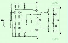
UAS version 7
at last
to avoid strange emphasis in VAS
it becomes necessary to minimize the current game
(transistors are much more similar as smaller)
then a spontaneous stage after the VAS done with mosfets
UAS suitable impedance so simple and effective - tested OK
(10K resistors on 25V dual)


at last
to avoid strange emphasis in VAS
it becomes necessary to minimize the current game
(transistors are much more similar as smaller)
then a spontaneous stage after the VAS done with mosfets
UAS suitable impedance so simple and effective - tested OK
(10K resistors on 25V dual)
Attachments
Very good!
Stefano
Very good ... bella grafica ... bono!
Love your images and graphics.
lineup
Lineup amplificadores fora - solo pro membres
----------------
hehe hehe
Stee said:at last
to avoid strange emphasis in VAS
it becomes necessary to minimize the current game
(transistors are much more similar as smaller)
then a spontaneous stage after the VAS done with mosfets
UAS suitable impedance so simple and effective - tested OK
(10K resistors on 25V dual)
Stee said:typical application
Stee said:let a small advertising
Stefano
Very good ... bella grafica ... bono!
Love your images and graphics.
lineup
Lineup amplificadores fora - solo pro membres
----------------
hehe hehe
grazie 1000
see another good modification to reduce load on VAS
and have true hi-end sound
http://www.esafono.it/mark331sch.jpg
http://www.esafono.it/mark331.jpg
never tested until comes mosfets by mail
see another good modification to reduce load on VAS
and have true hi-end sound
http://www.esafono.it/mark331sch.jpg
http://www.esafono.it/mark331.jpg
never tested until comes mosfets by mail
2SK213, 214, 215 216
2SJ76, 77,78,79
= Hitachi best lateral mosfet 😎 😎 😎 😎 😎 😎
My favora favor favourite transistors
HITACHI Data download from LineupAudio
http://lineupaudio.freehostia.com/pdf/contents.php
password = diyaudio
😉
Also visit the new audio forum with members join:
Lineup Audio forum
.
2SJ76, 77,78,79
= Hitachi best lateral mosfet 😎 😎 😎 😎 😎 😎
My favora favor favourite transistors
HITACHI Data download from LineupAudio
http://lineupaudio.freehostia.com/pdf/contents.php
password = diyaudio
😉
Also visit the new audio forum with members join:
Lineup Audio forum
.
The secret of good amplification
I have tested A700 from Lite (china - DIY Gene)
very good sound (thanks Mark)
schematic here http://www.esafono.it/a700.pdf
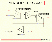
so my idea now is separate function
a- differential for correction error between demand
better use an OPA
b- voltage amplification
better use small transistors
mirror less
c- current amplification
better use a chain to 3 copules of final device
that does not lead to load the VAS
d- DC servo
important separate because viceversa compress signal
I have tested A700 from Lite (china - DIY Gene)
very good sound (thanks Mark)
schematic here http://www.esafono.it/a700.pdf
so my idea now is separate function
a- differential for correction error between demand
better use an OPA
b- voltage amplification
better use small transistors
mirror less
c- current amplification
better use a chain to 3 copules of final device
that does not lead to load the VAS
d- DC servo
important separate because viceversa compress signal
Attachments
- Status
- Not open for further replies.
- Home
- Amplifiers
- Solid State
- UAS - Universal Amplification Stage