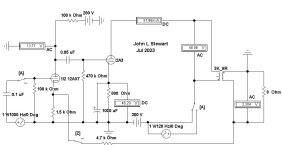
Typical 2A3 SE Amp PS Hum Interference A John L Stewart July 2023
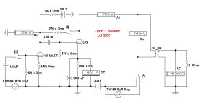
Simulation of a typical SE amplifier to show the effect of a One Volt PS hum. With or without Schade NFB. And what that looks like on the secondary of the OPT under load. Altho any working amp would not have One Volt of hum this value allows easy calculation to any other hum number.
The simulation has two switches to setup various conditions. On the Keyboard switch ‘A’ is a DPDT that allows looking at the hum only or switching to a normally driven amp. That way several calculations are possible. Switch ‘Z’ applies Schade NFB.
In Test 1 the one Volt of PS hum translates to 41.08 mv on the OPT secondary. In Test 2 Schade NFB is applied & the One Volt PS hum increases to 45.03 mv.
In Test 3 Switch ‘A’ is set to the other condition, the circuit becomes an ordinary amplifier. With switch ‘Z’ open there is no FB. Power output to the load is about 2.5 watts with a One Volt driving signal. The gain of the 2A3 is ~3.5.
In Test 4 the Schade NFB of ~5.6 db is applied by closing switch ‘Z’. Gain of the 2A3 remains ~3.5. But now the half AX7 must drive its 100K plate load & the following 2A3 grid resister of 470 K in parallel along with the Schade resistor. In the FB network the Schade resister looks like 270K / A+1 where A is the gain of the 2A3. So becomes 270K / 4.5 or 60K. The three resistances in parallel calc out to 34.7K , an intolerable load for half an AX7. All easy to do on an RPN calculater. 👍
Attachments

The 2A3 is a directly heated filament. Your drawing shows an indirectly heated cathode.
This is why 'simulations' are a waste of time in general.
Make a 2A3 power amp and get real results.
This is why 'simulations' are a waste of time in general.
Make a 2A3 power amp and get real results.
@JonSnell Electronic, that's a nonsense comment. Tube models do not simulate the heater, and the symbol can be anything you want, has nothing to do with the simulation. You can draw the tube as a hangman symbol, and it still works fine, what matters are the circuit connetions to the underlying symbol. But I can understand that simulation seems like magic for those who don't understand it ;-)
Jan
Jan
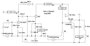
Interesting investigation. Did you draw any comclusions wrt the PSRR of the circuits, or a recommended way to minimise it?Typical 2A3 SE Amp PS Hum Interference A John L Stewart July 2023
Simulation of a typical SE amplifier to show the effect of a One Volt PS hum. With or without Schade NFB. And what that looks like on the secondary of the OPT under load. Altho any working amp would not have One Volt of hum this value allows easy calculation to any other hum number.
The simulation has two switches to setup various conditions. On the Keyboard switch ‘A’ is a DPDT that allows looking at the hum only or switching to a normally driven amp. That way several calculations are possible. Switch ‘Z’ applies Schade NFB.
In Test 1 the one Volt of PS hum translates to 41.08 mv on the OPT secondary. In Test 2 Schade NFB is applied & the One Volt PS hum increases to 45.03 mv.
In Test 3 Switch ‘A’ is set to the other condition, the circuit becomes an ordinary amplifier. With switch ‘Z’ open there is no FB. Power output to the load is about 2.5 watts with a One Volt driving signal. The gain of the 2A3 is ~3.5.
In Test 4 the Schade NFB of ~5.6 db is applied by closing switch ‘Z’. Gain of the 2A3 remains ~3.5. But now the half AX7 must drive its 100K plate load & the following 2A3 grid resister of 470 K in parallel along with the Schade resistor. In the FB network the Schade resister looks like 270K / A+1 where A is the gain of the 2A3. So becomes 270K / 4.5 or 60K. The three resistances in parallel calc out to 34.7K , an intolerable load for half an AX7. All easy to do on an RPN calculater. 👍
Jan
Nice work 👍
Can you perhaps try to simulate the effect of this hum reducing technique: https://www.tubecad.com/april99/page2.html
Can you perhaps try to simulate the effect of this hum reducing technique: https://www.tubecad.com/april99/page2.html
Hey JonS, good to know you are out there in cyber space keeping track of those of us who might defy Gravity & good engineering. But you missed the intention of this Sim, the title clearly states PS hum & that is reinforced by the position of the One Volt interference generator in the schematic. I’m confident that you have successfully interpreted many schematics in the past.
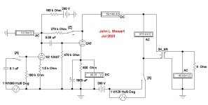
So continuing with this exercise, in Test A the Schade NFB circuit has been removed & replaced with a NFB connexion common in amplifiers of the socalled ‘Golden Age’ of vacuum tube amplifiers. Without NFB, the circuit performs essentially the same as in Test 1 as we might expect.
In Test B about 5.8 db of NFB is switched in, about the same degree as in Test 2 with Schade NFB. But in this circuit the hum at the OPT secondary is about half what it is without NFB, in contrast to the increased hum problem with the Schade connexion.
In Test C the gain of the 2A3 is still ~3.5. The load on the driving half AX7 is simply 100K in parallel with 470K, ~82.5K.
In Test D with 5.8 db NFB the load on the driver remains 82.5K, much less difficult to drive than while in the Schade circuit.
Which leads to the question, why would anyone building an amp use Schade NFB in this simple circuit? But many do now in contrast to the past.
In the next exciting episode I’ll have a look at the Damping Factor of these circuits. And use some real numbers for the resistance of the OPT primary & secondary. Those matter a lot.
JanD, I’ll run some Sims on the PSRRs as well.👍
These Daze my engineering skills are limited to felling dead trees & operating a 20 T log splitter. Grass cutting, a lot of it. And gotta replace a water softer & dishwasher, all of which were a lot easier when I was young. In olde age everything is a lot heavier. I think the Gravitational Constant has changed!😀
Attachments


John Broskies TubeCad had a lot of interesting ideas & was a popular read over several years,Can you perhaps try to simulate the effect of this hum reducing technique:
I'll have a look at that piece & see how it fits into this discussion.
One very good point JohnB made had to do with the opinion of some amateurs with regard to test equipment.
Some thought their work of art might be defiled or ruined if a connexion was made to TE.
Most often their amp tested nowhere as good as the owner thought it should. A big disappointment.😱
Attachments
Yes that would be of interest. The way this is normally done is that you impose an ac signal on B+ and look how much of it turns up at the output, with shorted amp input of course.JanD, I’ll run some Sims on the PSRRs as well.👍
BTW I made an error above when I said: "what matters are the circuit connections to the underlying symbol.
That should have been: "what matters are the circuit connections to the underlying model."
Jan
jhstweart9,
Test and Measurement Forever!
HP (You?); and Tektronix, Rohde & Schwarz, and Advantest (me).
My thanks to you from the other side of the Aisle, for all your Posts in Tubes / Valves.
Yes, all thread readers out there, listening tests too; and when possible . . . Properly executed Double Blindfold Listening tests.
Some of my amplifier designs sounded terrible, and measured very bad too. They got rebuilt into different topologies.
Keep life interesting.
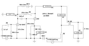
For these tests an OPT, the Hammond 125DSE has been connected to the circuit. And then tests for the internal resistance of the amp with & without normal NFB of about 6 db. The measurement results are as follows—
No NFB 8R load on OPT secondary, 4.07V
No Load on OPT Secondary, 5.76V
Rint = Delta E / Delta I……………….Delta E = 5.76V – 4.07V
And Delta I = 4.07V / 8R…………….0.51A
So Rint = 1.69 / 0.51…………………..3.31R
DF = 8 / 3.31………………………………………..2.41…………….about right for a 2A3 with Zero NFB.
With ~6 db NFB 8R load on OPT secondary, 2.208V
No Load on OPT Secondary, 2.525V
Rint = Delta E / Delta I……………….Delta E = 2.525V –2.208V
And Delta I = 2.208V / 8R…………….0.28A
So Rint = 0.32 / 0.28…………………..1.15R
DF = 8 / 1.15………………………………………..6.96…………….Better control of the lautscprecher
A 2V input will drive the 2A3 to 2.5 Watts with the NFB connected.
A One Volt Interference signal on the PS lead results in ~383 mV across the OPT primary.
That would be PSRR at that point of 8.3 db, we need a good PS filter on this one.
More later, same circuit but with Schade NFB for comparison.
Attachments
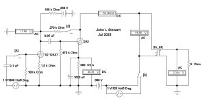
For these tests with Schade NFB an OPT, the Hammond 125DSE has been connected to the circuit.
And then tests for the internal resistance of the amp with & without Schade NFB of about 6 db.
The measurement results are as follows—
No NFB 8R load on OPT secondary, 4.07V
No Load on OPT Secondary, 5.76V
Rint = Delta E / Delta I……………….Delta E = 5.76V – 4.07V……………same as with common NFB
And Delta I = 4.07V / 8R…………….0.51A
So Rint = 1.69 / 0.51…………………..3.31R
DF = 8 / 3.31………………………………………..2.41…………….about right for a 2A3 with Zero NFB.
With ~6 db Schade NFB 8R load on OPT secondary, 2.801V
No Load on OPT Secondary, 2.125V
Rint = Delta E / Delta I……………….Delta E = 2.801V –2.125V
And Delta I = 2.208V / 8R…………….0.27A
So Rint = 0.32 / 0.27…………………..2.54R
DF = 8 / 2.54……3.14…………….About one half as in common NFB with same degree of NFB
A 2V input will drive the 2A3 to 2.5 Watts with the NFB connected.
A One Volt Interference signal on the PS lead results in ~890 mV across the OPT primary.
That would be PSRR at that point of 1.0 db, we need a very good PS filter on this one. 🙂
Results with the common NFB are clearly better. Something to think about as we build our amps.
More later, lets have a look at the AX7 loading by the Schade NFB,👍
Attachments

- Home
- Amplifiers
- Tubes / Valves
- Typical 2A3 SE Amp PS Hum Interference