Does anybody what type of TO3 outputtranssistors are used in a Class´s Audio DR-3 or maybe DR-2/DR-3B/DR-3 VHC.
Bias and DC offset are drifting in one channel so I can´t operate the unit properly.
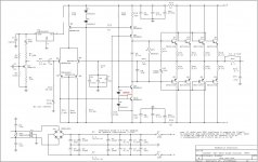
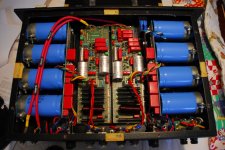
Do have the service manual and I know bias must be 0.8 Volts measured over a one of the big 10 Watt resistors between input PCB and big blue PSU lytics and DC ±4mv max.
Suggestion handwritten on the servicemanual is to substitute both the inputtransistors MPSA53 TO92´s located at Q3 and Q4 to stabilize the fluctuating DC by MSP8599´s.
Any suggestions?
Did listen to this amp with reduced bias (130 Watts intake fom AC instead of the 500 Watts specified and it sounded so wonderful that I would love to keep it!
Thans in advance,
Robert
Attachments
Addendum
I just switched all the outputtransistors from one channel to the other but the problem remains in the same channel.
Whenever I connect a dummyload to the problem channel the bias immediately doubles and the DC Offset goes from ±15 mV to -50mV or even higher.
The other channel remains stable.
I can see that in the problem channel all outputtransistors haven been replaced by new pairs of 11015/16 highcurrent Darlingtons and the original 5 MPS8599 by MPSA53´s. So it seems they already tried to solve this problem and did not succeed or the problem was only temporarly solved.
Any help would be great?
do you have a scope, that sounds like the amp is oscillating when a load is attached. A scope would help to check.
Check the zorbel cap and resistor, C9 ,C5-7 and D3/4.
check the rail resistorsR33/34.
If it is oscillating a Miller? cap (100pf) across BC of Q10 may help
Check the zorbel cap and resistor, C9 ,C5-7 and D3/4.
check the rail resistorsR33/34.
If it is oscillating a Miller? cap (100pf) across BC of Q10 may help
do you have a scope, that sounds like the amp is oscillating when a load is attached. A scope would help to check.
Check the zorbel cap and resistor, C9 ,C5-7 and D3/4.
check the rail resistorsR33/34.
If it is oscillating a Miller? cap (100pf) across BC of Q10 may help
Thanks!
I´m not a technician and do not have a scope but all the caps you mentioned are those red and green WIMA´s.
The Zobel cap is C14 and the resistor is R31 inside the 2.5mH inductor probably?
The only way to check that resistor is to desolder the inductor I think.
With D3/4 you mean the Diodes CR-3 and CR-4.
On the attached image you can see that these have been replaced also in the problem channel.
Attachments
Why don't you write to Classe' customer service? They have always been very helpful with me. The DR3 is a highly regarded amp and needs a proper repair to show his virtues 🙂
when I repaired mine, I contacted Classe and they sold me all original parts and sent me a schematic and the whole nine yards! they are very nice!
when I repaired mine, I contacted Classe and they sold me all original parts and sent me a schematic and the whole nine yards! they are very nice!
Glad to here that!
If I only knew what to order 😱
Miller Cap and Scope
I'm bidding on a Tektronix 2225 right now.
Miller cap like this:
do you have a scope, that sounds like the amp is oscillating when a load is attached. A scope would help to check.
Check the zorbel cap and resistor, C9 ,C5-7 and D3/4.
check the rail resistorsR33/34.
If it is oscillating a Miller? cap (100pf) across BC of Q10 may help
I'm bidding on a Tektronix 2225 right now.
Miller cap like this:
Attachments
Last edited:
Thats the miller cap I was thinking off. It can tame some problems.
I would not be without mine, a very old Hameg HM812 🙂 probably 30 years old or more but still going strong. Maybe not as fancy as a DSO but shows oscillations. Good luck with the bidding.
I would not be without mine, a very old Hameg HM812 🙂 probably 30 years old or more but still going strong. Maybe not as fancy as a DSO but shows oscillations. Good luck with the bidding.
They are Darlington Output Transistors.
What an awfully unstable design!
Great!
The designer Dave Reich said that these were powertransistors that other manufacturers of high/end audio wouldn't consider to use....
The Miller cap did not help I must go on...
Unstable you say? These were one of the few that could drive the famous 1 ohm Apogee Scintilla's
Unstable you say? These were one of the few that could drive the famous 1 ohm Apogee Scintilla's
Is that a recomendation then, a 1R load? Who owns 1R speakers that are fed with 16mm cable to avoid power loss?
High current drive yes but lots of linearity errors and the quiescent current varies as the output is driven ... need I go on?
Is that a recomendation then, a 1R load? Who owns 1R speakers that are fed with 16mm cable to avoid power loss?
High current drive yes but lots of linearity errors and the quiescent current varies as the output is driven ... need I go on?
Yes please!
It´s getting weirder!
As soon as I operate the leftchannel alone (rightchannel AC fuse disconnected) everything seems fine. I can stabilize the DC Offset at ± 1mV and the bias remains stable at 400mV also.
As soon as I reconnect the rightchannel the bias in the leftchannel more the doubles in a split second and the DC offset in the leftchannel goes to -150 mV immediately and settles after a few seconds at 40 mV.
I have no glue to be honest what is the case of this strange behaviour.
Simple solution:
I desoldered the only connection between the left- and rightchannel (the small orange wire at the back) soldering points denoted as ´E2´ and ´bridge´ and voilà both channels happy and stable...
Can´t bridge now off course but hey one stereo will be able to drive my speakers easily.
It´s a bit dissatisfying of course and I have to find the offender in the small bridging part of the rightchannel frontend someday...🙄
Attachments
- Status
- Not open for further replies.
- Home
- Amplifiers
- Solid State
- Type of outputtransistors in a Classé Audio DR-3


