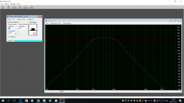
I have simmed a bandpass with 9 Mivoc here.
4 vents are used and they are only 107 mm long and the velocity is ok.
So you have to close the gabs on each side of the Vifa collums and insert 4 vents 0.047x0.047 and 0.107 long .
4 vents are used and they are only 107 mm long and the velocity is ok.
So you have to close the gabs on each side of the Vifa collums and insert 4 vents 0.047x0.047 and 0.107 long .
Attachments
I have simmed a bandpass with 9 Mivoc here.
4 vents are used and they are only 107 mm long and the velocity is ok.
So you have to close the gabs on each side of the Vifa collums and insert 4 vents 0.047x0.047 and 0.107 long .
Hey, that's just great! Many thanks! Will make a drawing ASAP.

BTW: 0,047 and 0,107 is in meters or inches? Meters, I hope...
Last edited:
Hey, that's just great! Many thanks! Will make a drawing ASAP.
BTW: 0,047 and 0,107 is in meters or inches? Meters, I hope...
All metric, yes
Hi Fluid,
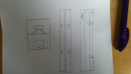
I'm not sure I fully understood. Do you mean something like this? (see attached)
Sometimes my english just fails me 🙁
I'm not sure I understand your drawing but here are some images to try and explain it.
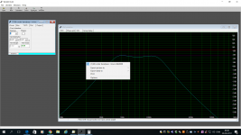
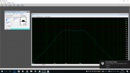
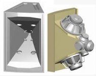
This is the way that winisd shows a 4th order bandpass, the port is where the woofer exits.
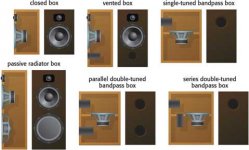
Here is an image showing a few different types with the front panels
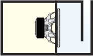
What I mean by mounting the woofer flat to the baffle is like this image of a synergy. You can see where the woofers mount to the horn and exit through ports in the horn wall. The volume of air under the cone is the front chamber, the diameter of the holes is the port and the thickness of the baffle is the length of the port.
Does this make sense?
And I'm sure your english is far superior to my German 🙂
Attachments
You could do it like that.Thanks, this makes perfect sense. I just scratch my head how to incorporate this into my 9 woofers high line array... and came up with something like this (extremely crude sketch):
I was thinking more like your first image but to mount the woofer directly to a baffle (behind the TC9 Cabinet) and vent into the short horn.
As promised...
I think you are trying to sketch what I was thinking, but you need a baffle behind the Vifa enclosure where the Mivoc´s are mounted so you have a back and a front chamber for the Mivoc´s

I can't get Bassboxx to agree with that sim, it gives a very narrow bandwidth and huge vent air speed.Maybe this is even better.
I preferred the idea of a line of woofers rather than one with a very big chamber front and back. The maximum spl of a system like that will be limited and for a PA that is important.
Fun stuff, we could even make it a 3 way with an array of (many) tweeters. 😀
😱
Don't even mention it! 😛
I can't get Bassboxx to agree with that sim, it gives a very narrow bandwidth and huge vent air speed.
I preferred the idea of a line of woofers rather than one with a very big chamber front and back. The maximum spl of a system like that will be limited and for a PA that is important.
You were faster than me: having a low-end-line seems so much more intrigueing than having a subwoofer in the same closet as the full ranges.
Like this
This is exactly what I posted yesterday 🙂
The light grey area is the closed front.
Attachments
Last edited:
Oh - ok I see now. Great.This is exactly what I posted yesterday 🙂
The light grey area is the closed front.
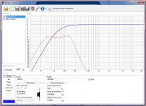
I think I might have a little reservation concerning this design. The mouth area of the 4 vents is pretty small. Even though WinISD says the velocity is ok small, the combined area of the vents is only 81 sq.cm!
In order to move the air in a big room there has to come a LOT of air out (and in) of these vents. 😕
This is exactly what I posted yesterday 🙂
The light grey area is the closed front.
I think you have the wrong orientation of the vents. They are 47x47 in the opening and 107 long.
- Status
- Not open for further replies.
- Home
- Live Sound
- PA Systems
- Two-way line source for church sound