Hi:
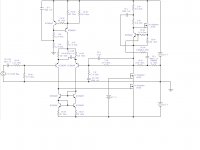
Here is my new design of a two stage amplifier with output mosfet run in class A. Output power is 4,8 W into 12 ohms for input of 2 V RMS. Máx Output power is 30 W into 8 ohms. Z input is 5k9 aprox.
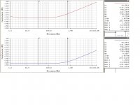
In the attached file are the curves of total distortion vs. frecuency into 6, 8 and 12 ohms and for input of 0,001 V until 5 V RMS.
Sorry for my english!
Here is my new design of a two stage amplifier with output mosfet run in class A. Output power is 4,8 W into 12 ohms for input of 2 V RMS. Máx Output power is 30 W into 8 ohms. Z input is 5k9 aprox.
In the attached file are the curves of total distortion vs. frecuency into 6, 8 and 12 ohms and for input of 0,001 V until 5 V RMS.
Sorry for my english!
Attachments
Last edited:
In my real life project, i´d put stopper resistors with every IRF150N in the schematic: maybe around 100 to 390 ohms.
The sound with my monitors is wonderful!.
Thanks
The sound with my monitors is wonderful!.
Thanks
Last edited:
Hi:Here is my new design of a two stage amplifier with output mosfet run in class A.
Hi, what is a voltage source 21,7V to the gate of cascoded IRF150? How did you make this?
I didn´t put the cascode voltaje made with one fix resistor + potentiometer + zener + diode in series between negative rail and ground, only for a bit clear schematic.
The power supply is made with 4 transformers: 4 units x 220 V/24 V/240 VA (two for channel). Total of 960 VA for 30 W + 30 W RMS aprox máx in class A.
28200 uF per rail and per channel. Total of 112800 uF.
4 bridges diodes of 15A.
PSRR is around 93,7 dB.
Any sugestion?
The power supply is made with 4 transformers: 4 units x 220 V/24 V/240 VA (two for channel). Total of 960 VA for 30 W + 30 W RMS aprox máx in class A.
28200 uF per rail and per channel. Total of 112800 uF.
4 bridges diodes of 15A.
PSRR is around 93,7 dB.
Any sugestion?
Last edited:
Normally, i run the amp at 4,8 W + 4,8 W RMS into 12 ohms with a greater dynamic range than 8 ohms.
Member
Joined 2009
Paid Member
Very nice circuit - your output stage is very close to something I am considering to use with tube driver, except I was not (until now) thinking of using the Aleph current source that you have employed. The Aleph is very well thought of, not surprised you find it sounds so good.
What is the purpose of the capacitor between emitters of the LTP input pair ?
What is the purpose of the capacitor between emitters of the LTP input pair ?
Hi Bigun:
The objective of this capacitor is to help lower the distortions mainly to the low frequency side.
It's something I checked in my many simulations.
Thanks
The objective of this capacitor is to help lower the distortions mainly to the low frequency side.
It's something I checked in my many simulations.
Thanks
Shouldnt you be more concerned about the high frequency distortion. Try a inductor of around 7 to 10 uH.
That capacitor connected across the emitters forms a low impedance at high frequency and raises the gain of the diff pair. This may get you Lowe distortion, but you will have then probably have to deal with reduced stability margins and possible TIM. I'd leave it out - its always better to trade a bit of distortion for stability in my view.
Hi:
Here is my new design of a two stage amplifier with output mosfet run in class A. Output power is 4,8 W into 12 ohms for input of 2 V RMS. Máx Output power is 30 W into 8 ohms. Z input is 5k9 aprox.
In the attached file are the curves of total distortion vs. frecuency into 6, 8 and 12 ohms and for input of 0,001 V until 5 V RMS.
Sorry for my english!
This approach goes in direction to my proposal about
http://www.diyaudio.com/forums/pass...adin-no-memory-distortion-ultimate-aleph.html
Bonsai: The capacitor in conjunction with other elements reduces the phase margin, but improves significantly the composition of the distortion. Can be altered as needed.
AndrewT: The cascode at the output reduces the THD to significant levels. At the same time reduces the maximum output excursion. The intention is that the output excursion is sufficiently far from the supply voltage (in normal use) to effectively use the slew rate achieved by the system. Unfortunately, you pay with low efficiency. I use high output impedance instead of the traditional 2, 4, 6 or 8 ohms, because in this same way I get a wider dynamic range. I give an example, for every doubling of output impedance get about 6 dB higher range, using the same interconnect resistance. For example: With 16 ohms achieving a range around 24 dB higher than 2 ohms, changing only the voltage and current relationships!. I designed this amplifier to behave more appropriately in 12 ohms and low levels of distortion achieved mainly in the range of voices.
There is a small error in the first post and it's just that you can achieve a maximum power of about 30 W per channel into 12 ohms instead of 8 ohms as mentioned. In the attachment is all correctly specified. It was only for my trouble.
The idea is to try it and discuss the results.
tiefbassuebertr: can you think that my design really goes in direction to your proposal? Tell me more.
Sorry for my english!
regards
Last edited:
- Status
- Not open for further replies.
- Home
- Amplifiers
- Solid State
- Two Stage Amplifier with Mosfet in class A