One amp died when Main positive and negative power in crossed, and the other failed with a multimeter attached while connected to speaker terminals while loaded. Of these two are the components I have to replace with bd139 & bd140, IRFP064N, IRF640. The first amp I have replaced with bd139 and bd140, new 47ohm resistors & IRFP064N, and repaired a trace under the coils.
I have the other amp all with the same symptoms, but additionally, the pwm/protection board has some failed components I have been scouring the forum for. I found here the schematic to help Identify resistor values but no ID on the transistor in position Q5. I dont know what Q5 is, a pnp transistor or linear voltage regulator? https://www.diyaudio.com/community/...-type-3-protectionmarkedtype3-01-pdf.1270452/
Im also reading a handful of odd resistor values on the pwm board as well.


Where I can get a hold of a replacement board? Tracing Q5 to r10A (top), bottom middle leg to pin 1, left leg to C1898, But What does the right leg lead to seeing as it blown the trace? Probing what little left of the trace shows that its connected to pin1(bottom leg & top). What is the transistor of Q5?
I have the other amp all with the same symptoms, but additionally, the pwm/protection board has some failed components I have been scouring the forum for. I found here the schematic to help Identify resistor values but no ID on the transistor in position Q5. I dont know what Q5 is, a pnp transistor or linear voltage regulator? https://www.diyaudio.com/community/...-type-3-protectionmarkedtype3-01-pdf.1270452/
Im also reading a handful of odd resistor values on the pwm board as well.
Where I can get a hold of a replacement board? Tracing Q5 to r10A (top), bottom middle leg to pin 1, left leg to C1898, But What does the right leg lead to seeing as it blown the trace? Probing what little left of the trace shows that its connected to pin1(bottom leg & top). What is the transistor of Q5?
Last edited:
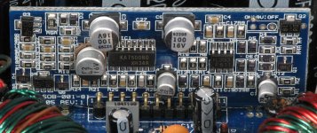
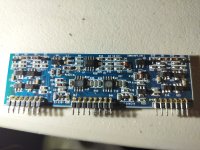
All the questions pertain to one amp, the others purpose is to show i have a good duplicate board if necessary for gathering measurements, now i can order that part and follow up the thread.
Do you believe that that's the last problem? It only controls the relay. Do you have clean audio up to the relay?
refernecing my good board, So it seem the gate is connected to pin 5 and also r25, r26, r27, and r28. The bad board seems to make these proper connections, but whats the proper point to probe for signal?
Last edited:
You would look for audio on L205 and L208.
You should also check D201 to confirm that it's not shorted.
You should also check D201 to confirm that it's not shorted.
Are L205 and L208 the power supply inductors? I found D201 and it doesn't short to the negative main rail and across d201 reads 155ohms.
L205 & L208 may be covered by CA glue. i will report back when i retrieve signal for high/low output gates, and power supply mosfet waves & DCV
L205 & L208 may be covered by CA glue. i will report back when i retrieve signal for high/low output gates, and power supply mosfet waves & DCV
Last edited:
Looking at your board, it appears that it's different from the diagram you posted.
What's the part number on the output board in this amp?
You could check for audio on the terminals of the relay. You could probably also check on the small inductor near the relay.
What's the part number on the output board in this amp?
You could check for audio on the terminals of the relay. You could probably also check on the small inductor near the relay.
I meant to say "the source of Q5 is connected to pin 5 and also r25, r26, r27, and r28." The ouput board is labeled DWM1216F_V20
Last edited:
Voltage steady at 12.6v and drawing no more than 1.5amps. So far I replaced mosfets, put in new resistors, fixed pwm board. Driver waves looked good. While i had the board out I saw that the wave on the source of the output FETs resembled a sine wave. I then probed the gate of the output mosfet and somethign went wrong with the amp. The voltage immediately sagged to 8.6v and current draw spiked to 3.5amps.
I removed the rectifiers and replaced the drivers again with bd139/140 counterparts. The issue still persists. Once the remote is on the source at the FETs drops to 8.6volts and the gate drive wave appears to be turning on and off instantaneously going between 1v-3.5v. What component would cause these symptoms?
I removed the rectifiers and replaced the drivers again with bd139/140 counterparts. The issue still persists. Once the remote is on the source at the FETs drops to 8.6volts and the gate drive wave appears to be turning on and off instantaneously going between 1v-3.5v. What component would cause these symptoms?
Please leave a blank line between sentences.
Do the circuit board designations in your amp match that of the AQ2200 diagram that was posted?
Do the circuit board designations in your amp match that of the AQ2200 diagram that was posted?
The labeling matches perfectly. but some of the resistor values seem off to me.
Such as the two resistors at the output FET's gates. R205 read 10k, as it should, but the other, R204, is reading 20K instead of 150K.
R112(10K) is read as 40K, R111(10K) is 85K. R201 off the daughter board is correct at 150K.
Tracing low side output to IC201, daughter board. I cant make out what U2 and U3 are.
Attachments
Last edited:
R205 is supposed to be 10 ohms, not 10k. Check it out of the circuit.
R204 is reading in parallel with the other 100k pulldown resistors.
R111 and R112 are insignificant but will likely vary with the position of the pot connected to them.
R204 is reading in parallel with the other 100k pulldown resistors.
R111 and R112 are insignificant but will likely vary with the position of the pot connected to them.
You are correct is is 10 ohms. double checked. the AQ schematic seems correct, as other threads on the hifonics 26xxd lineup where it has been posted previously. Once i got the board running everything had seemed perfectly fine, except instead of seeing a square wave on the output FET drain, I was seeing a sine wave. I wasnt thinking straight when I probed the gate side of the FET and caused this mishap. Any thoughts?
When you view the drain waveform on the PS FETs, do you see a clean square wave?
With no RCAs plugged into the amp, what's the resistance (no power applied) between the primary ground and the secondary center tap (or the negative speaker terminal)?
With no RCAs plugged into the amp, what's the resistance (no power applied) between the primary ground and the secondary center tap (or the negative speaker terminal)?
I just removed the main board from the pcb. Please correct me if im wrong, but isnt the smaller board called the PWM/driver board and the larger 22 pin
board is the daughter? Could I take these measurements at the PS FETs with the 22 pin board still out of the amp?
The Resistance between ground and negative speaker terminal is 0.2-0.3 ohms and the drive wave(drain) PS FET is a messy slumpy hill now, whereas
before when i had it working prior to the screwup was perfectly square.
The Wave of the PS FET gate is a square wave, resembling my previous oberservance.
Last edited:
People use various terms. Daughter board, driver board... can apply to any board (maybe not a preamp board) that plugs into the main board.
I'd refer to them as the power supply driver board and the audio driver board.
Do you have a clean square wave on pins 9 and 10 of the TL494?
I'd refer to them as the power supply driver board and the audio driver board.
Do you have a clean square wave on pins 9 and 10 of the TL494?
- Home
- General Interest
- Car Audio
- Two Hifonics BXI-2610D, one repaired, another component ID PWN