Hi to all,
i would use the WM8804 to convert the S/PDIF to I2S (16bit). The I2S should feed my TDA1541A NOS DAC.
Unfortunately i have no sound output 🙁 , independent if i set the I2S to 16 or 24 bit (AIFCONF0 1 or 0).
Malka07 use the same DAC pcb´s from me and have also no luck.
The connections are as follows:
LRCLK to TDA Pin1
BCK to TDA Pin2/4
Data to TDA Pin3.
Can someone help?
With my Teradak X2 USB to I2S converter, everything works fine!
Best regards,
Oliver
Last edited:
Is there any output on the pins of the WM8804? Check for a LRCLK (pin15) at least.
Also, note that the datasheet has an example for 16-bit right-justified audio, not I2S. This bit me once trying to use a WM8805...
I don't know the twisted pear board sufficiently well to be of any other advice.
Good luck!
Also, note that the datasheet has an example for 16-bit right-justified audio, not I2S. This bit me once trying to use a WM8805...
I don't know the twisted pear board sufficiently well to be of any other advice.
Good luck!
Hi Oliver,
I've checked my setup(TP 8804 into TDA1541a NOS) and had a look at the TDA data sheet and it looks like pin27(OB/TWC) on the TDA has to be pulled high(connected to pin28/VDD/+5v) to allow it to accept multiplexed two's complement/I2S input. Might be worth checking in your setup.
Regards
Cornelius
I've checked my setup(TP 8804 into TDA1541a NOS) and had a look at the TDA data sheet and it looks like pin27(OB/TWC) on the TDA has to be pulled high(connected to pin28/VDD/+5v) to allow it to accept multiplexed two's complement/I2S input. Might be worth checking in your setup.
Regards
Cornelius
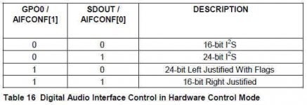
That´s the settings we use. On both 24Bit & 16Bit I2S no sound 🙁
An externally hosted image should be here but it was not working when we last tested it.
Last edited:
hi
I am using WM8805, WM8742, but I think this should be good to 8804
WM8804--TDA1541
16bit I2S hardware
1--H
2--L
3--L
4--L
5--Unlock(3v3-10k-led)
6--
7--3V3+
8--AGND
9--
10-Xtal
11-Xtal
12-Data out
13-
14-Bclk-out
15-LRck-out
16-
17-
18-DGND
19-3V3+
20-Spdif-IN
I am using WM8805, WM8742, but I think this should be good to 8804
WM8804--TDA1541
16bit I2S hardware
1--H
2--L
3--L
4--L
5--Unlock(3v3-10k-led)
6--
7--3V3+
8--AGND
9--
10-Xtal
11-Xtal
12-Data out
13-
14-Bclk-out
15-LRck-out
16-
17-
18-DGND
19-3V3+
20-Spdif-IN
Can you please confirm there is at least LRCK signal? (if you have oscilloscope, that is). If you don't have oscilloscope, simply measure DC from LRCK to GND and report back. Measure DC with and without music playing.
Also, what are the status LEDs saying? All off?
Last thing which comes to mind: is the DAC powered from the same supply? If not, you might need to also connect the GNDs of the 2 boards?
Also, what are the status LEDs saying? All off?
Last thing which comes to mind: is the DAC powered from the same supply? If not, you might need to also connect the GNDs of the 2 boards?
Can you please confirm there is at least LRCK signal? (if you have oscilloscope, that is). If you don't have oscilloscope, simply measure DC from LRCK to GND and report back. Measure DC with and without music playing.
Also, what are the status LEDs saying? All off?
Last thing which comes to mind: is the DAC powered from the same supply? If not, you might need to also connect the GNDs of the 2 boards?
Hi and thanks for your help.
I have the same dac as Oliver(Dvb-projekt) and am also having the same problem. I dont have an oscilloscope, but i measured dc from LRCK to GND with and without music playing and both times i got 1.64v.
All LEDs are green when a coax cable in connected to the dac regardless of if music is playing or not. If the coax is disconnected then all lights are red except non audio which remains green.
I have Gnd on my Twisted Pair board connected to Gnd on the dac board.
Pictures of the dac can be seen in this thread along with Board layouts etc...maybe that will help too.
http://www.diyaudio.com/forums/group-buys/167414-reference-tda1541a-dac-i2s-bus-architecture.html
Page 1 shows the board layouts....and page 31 onwards, are pics of my dac with the problems im having.
Thank you all, for your kind help...i really would like to get to the bottom of this, and im sure Oliver would too.
Alon
Alon,
i´ve got an advice from John (ecdesigns) to our problem.
I could test it this evening. Perhaps your are able to test this earlier.

i´ve got an advice from John (ecdesigns) to our problem.
Hi Oliver,
It seems highly unlikely that a batch is not working.
WM8804 typical supply voltage equals 3.3V. The I2S attenuators you are
using are designed for 5V TTL levels only. This could also explain why
there is no sound with this particular module.
You could temporarily remove / bypass the I2S attenuators to see if
this is causing the problems. This could be done easiest by bypassing
the series resistors for DATA, BCK and WS.
I could test it this evening. Perhaps your are able to test this earlier.
Hi, I have similar problem using Y1 USB-to-I²S converter. No sound, but when bypassing I2S attenuators I got sound. Y1 USB-to-I²S converter supply voltage is 3.3V. What now ?
I got some interference, I think because I2S cabling and I don't have sound stage so I connected headphones directly to DAC output after IV resistor, or headphones quality is poor. Sound is normal.
I´ve looked deeper on the three modules (TP WM8804, Y1 PCM2707 & X2 TE7022). 
All three IC´s runs with 3.3V, so that´s not the difference.
The X2 is the only one, witch have a BUS Buffer (74HC125) between the converter IC and the I2S output.
On the Twisted Pear and the AMB Y1 pcb lacks this buffer.
I will try to insert such a buffer IC between the output of my TP WM8804 and the I2S input of the DAC module in the next days and report the result.
I have made some quick measurements with my oscilloscope:
Left: Teralink X2 BCK - Right: TP WM8804 BCK
Left: Teralink X2 LRCK - Right: TP WM8804 LRCK
Left: Teralink X2 Data - Right: TP WM8804 Data
Independent from the signal quality, any thoughts?
It seems that the Buffer in the X2 made a bit more output voltage.
Left: Teralink X2 BCK - Right: TP WM8804 BCK
An externally hosted image should be here but it was not working when we last tested it.
An externally hosted image should be here but it was not working when we last tested it.
Left: Teralink X2 LRCK - Right: TP WM8804 LRCK
An externally hosted image should be here but it was not working when we last tested it.
An externally hosted image should be here but it was not working when we last tested it.
Left: Teralink X2 Data - Right: TP WM8804 Data
An externally hosted image should be here but it was not working when we last tested it.
An externally hosted image should be here but it was not working when we last tested it.
Independent from the signal quality, any thoughts?
It seems that the Buffer in the X2 made a bit more output voltage.
Hello dvb-projekt
Did you succeed to made it work good ?
Thank
Bye
Gaetan
Hi Gaetan,
sorry for the late response, but i forgot to post it here. 😱
Read HERE about the solution.

Hi Gaetan,
sorry for the late response, but i forgot to post it here. 😱
Read HERE about the solution.
Hello
Thank you
Bye
Gaetan
- Status
- Not open for further replies.
- Home
- Source & Line
- Digital Source
- Twisted Pear S/PDIF WM8804 Transceiver Module on TDA1541A problem