Hi All, Greetings.
2 years back bought a new bookshelf speaker, but found its tweeter were too quiet, causing muffled mid-high freq. The speaker is bi-wirable, so I connect bi-wire to my amp's Speaker A/Speaker B. When running the tweeter on its own, I can hear it but it was a little quiet (less energetic), once switch on mid-bass (usage of bi-wiring), it will overpowering the tweeter, causing the entire sound spectrum to go low-mid to low. It was like a layer of cotton blocking the tweeter, restricting its output.
So recently I swapped the crossover with another smaller bookshelf from same company, now the speaker transformed by opening-up highs and sing, sounds good! So I thought of modifying the original crossover.
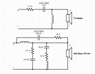
Referring to my attachments, the original crossover seems to have higher resistor values and more resistor and capacitor on the tweeter section compare to swapped unit, I'm not sure how it works. I was thinking to lowering down R1 to 3 ohm and R2 to 1.5 ohm, is this a good start? Speaker Spec as below:
Original Speaker:
2 way bookshelf speaker
165mm mid-bass driver
2kHz crossover
45Hz - 30kHz spec
The Donor's Speaker:
2 way bookshelf speaker
130mm mid-bass driver
3kHz crossover
58Hz - 20kHz spec
Thanks.
2 years back bought a new bookshelf speaker, but found its tweeter were too quiet, causing muffled mid-high freq. The speaker is bi-wirable, so I connect bi-wire to my amp's Speaker A/Speaker B. When running the tweeter on its own, I can hear it but it was a little quiet (less energetic), once switch on mid-bass (usage of bi-wiring), it will overpowering the tweeter, causing the entire sound spectrum to go low-mid to low. It was like a layer of cotton blocking the tweeter, restricting its output.
So recently I swapped the crossover with another smaller bookshelf from same company, now the speaker transformed by opening-up highs and sing, sounds good! So I thought of modifying the original crossover.
Referring to my attachments, the original crossover seems to have higher resistor values and more resistor and capacitor on the tweeter section compare to swapped unit, I'm not sure how it works. I was thinking to lowering down R1 to 3 ohm and R2 to 1.5 ohm, is this a good start? Speaker Spec as below:
Original Speaker:
2 way bookshelf speaker
165mm mid-bass driver
2kHz crossover
45Hz - 30kHz spec
The Donor's Speaker:
2 way bookshelf speaker
130mm mid-bass driver
3kHz crossover
58Hz - 20kHz spec
Thanks.
Attachments
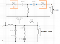
You can't touch R2, as it is combined with the driver impedance presented to the crossover. Changing its value will change the crossover point.
R1 can be moved up and down a bit, but be warned that this affects the phase relationship between the drivers. This will also be exacerbated by the fact that the crossover is in the middle of the vocal range, and you will lose a bit of coherence between the drivers (assuming it was coherent in the first place).
The crossover looks fairly well-designed. It is possible that the larger speaker was meant to be played louder and far away from walls, as such speakers are. You might be getting some proximity boost depending on room and listening position.
You could start by knocking down R1 with a small parallel resistor, say 20 ohms and see what that does. Another thing to try is place a small (<1uF) capacitor across it to give a slight lift to the absolute top end. This usually does not mess up the crossover point, while still adding a bit of sparkle in the top octave.
Hi Sangram, thanks for the advise, great to know the starting point.
Any reason why using 20 ohm parallel to R1 instead of replacing it with smaller resistor, say 3.6 ohm?
Any reason why using 20 ohm parallel to R1 instead of replacing it with smaller resistor, say 3.6 ohm?
I'd just put a jumper across R1 and have a listen. Tweeter too loud now? Then try some values less then 4.7R to tune it. Listening to it without R1 will tell you were you need to go.
Thanks Pano and Sangram, luckily I ask here, else I will start messing around R2 for a start, haha.
You're welcome.  Shorting R1 is going to increase tweeter output by 2-3dB on an 8 ohm driver - which isn't huge. It may be all you need.
Shorting R1 is going to increase tweeter output by 2-3dB on an 8 ohm driver - which isn't huge. It may be all you need.Any reason why using 20 ohm parallel to R1 instead of replacing it with smaller resistor, say 3.6 ohm?
Because you would not know what the target value is. Using larger value resistors one at a time will help you tune to the eventual value you need.
You can also use Pano's advice and go the other way.
Oh, didn't expect the 4.7 ohm differs so little on tweeter SPL output.You're welcome.
Well it would be more for a 4 ohm tweeter, of course. But think about current flow thru 4.7+2.2+8 ohms. Nearly 15 ohms vs 10 ohms without R1.
I'd say give it a try, if it's too loud with R1 bypassed than you can work on the value needed by using the method Sangram mentioned.
I'd say give it a try, if it's too loud with R1 bypassed than you can work on the value needed by using the method Sangram mentioned.
Quite logic using the sum up, overall changes percentage is quite less. Can I know measure the tweeter to know its resistance ohm by using multimeter? Is this method accurate?
Yes, you can measure with an ohm meter to see the DC resistance. Although that won't give you the actual impedance of the tweeter it will give you a clear indication of whether it's an 8 ohm or 4 ohm tweeter. An 8 ohm tweeter is usually around 6 ohms DC.
2-3dB can be a significant difference. It depends how close you are to begin with.Oh, didn't expect the 4.7 ohm differs so little on tweeter SPL output.
Hi All, I have measured the tweeter and woofer, tweeter 4 ohm woofer was 4.3 ohm.
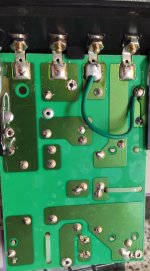
The crossover component was tight and factory hot glued, so I try to maintain its originally, using a short wire bypass from the back soldering.
Now the direct comparison with another speaker using swapped crossover:
Both tweeter SPL sounds the same, hmm why is this?
Modded has obvious better midrange, but with prominent background "noise"?
Modded sounds forward, while swapped unit sounds a little laid back.
Swapped unit treble sounds bite, it was laid back but higher frequency?
Modded unit treble less bite, it has more sound but not higher frequency.
Sorry for my layman explanation. So next is that mean I need to add parallel resistor (I try not to temper the original 4.7 ohm as it was hot glued) to filter out the prominent background noise?
Attachments
What you seem to be experiencing is a forward shift in the tweeter phase, which would be common for the arrangement you've made.
What you're trying to achieve is also not really possible without measurements of the individual drivers and the inductors in the crossover.
To keep things simple, I would try removing the short, and use pink noise to tune the speaker by trying a few different combinations of R+C in parallel with R1.
It is unlikely that you will be able to match a single 1.5ohm resistor's padding with any chosen combination. It is also likely that any modification will be correct if the original speaker design was already correct in phase and frequency terms.
Parallel resistor will bring up the total tweeter output, whereas parallel cap will bring up only the last octave. You should add resistors till you get the midrange to sound right, then add capacitors till you get the top octave right.
All of these options will mangle the phase response a bit, which will make the tweeter sound forward (this is what actually happens). To even this out, you can reduce the value of the 4.7uF cap or increase the 12uF cap (which can be achieved by using parallel capacitors, and will slightly affect the crossover point). I don't think it will be needed as the changes in phase are usually very small for even largish variations of the first resistor.
Thanks Sangram for detailed explanation.
"It is unlikely that you will be able to match a single 1.5ohm resistor's padding with any chosen combination."
I would like to ask, any reason to achieve 1.5 ohm?
"It is unlikely that you will be able to match a single 1.5ohm resistor's padding with any chosen combination."
I would like to ask, any reason to achieve 1.5 ohm?
Now I thought of another method, remain the 4.7 ohm shorting wire, as my speaker is bi-wireable, I can get a few resistors to try it, easily connect through the terminal.That is close to the value in the swapped crossover, is it not?
- Home
- Loudspeakers
- Multi-Way
- Tweeter too quiet, need help modify crossover