I was rewiring my xovers today and needless to say dropped one and broke it.I have been experimenting with different tweeters in these huge old fisher cabs.I have a 3-way Eminence cross over and the drivers are Eminence 15" woofers ,Pioneer 5 1/2" mid and now I need new tweeters.I have put Infinity and a unknown brand in them and they are all too bright with a lot of sibilance.The tweeter i broke was a KLH from a model 9912 liqued cooled dome.This was the best match so far for this setup I had found.Any good suggestions for what to replace the tweeters with.I am looking for a good clean (not real bright) tweeter.Any help would be appreciated.the KLH gave good clean, crisp,detailed sound and that is what i am looking for.Thanks
before you buy any new tweeters
If you still have any of the old tweeters you have tried, it would be worth (If you haven't tried this allready) trying to attenuate them. The problem could simply be that the tweeters are way more efficient than the other drivers.
do a search on LPAD and you should get the idea. If you have the specs on the drivers all the better, for instance if you have a tweeter rated at 93db efficiency and a woofer rated at 89db as a starting point you could try attenuating the tweeter by 4db (may be too much, but somewhere to start).
You can make your own with a couple of resistors, or you can buy variable ones (not so cheap an option).... the variable ones have the advantage that you can keep trying different settings till you find something you like.
Regards,
Tony.
Thanks for the advice .I bought a pair of variable resistors from radio shack and installed them in the cabinets.I backed off the tweeters a half a turn (just enough to bring it down to the level of the mid) and now it is nice and smooth and the sibilance has disapeared.What a difference.Thanks again.
No worries. Glad it's made an improvement, I may have given slightly the wrong impression when I said "variable ones" I was talking about variable LPADS, but if the variable resistors have done the trick then I guess that's ok 🙂
Regards,
Tony.
edit: I hope that they were pretty high powered variable resistors???? If not you better not crank the volume up too high! Might be best to measure the value and replace them with some 5 or 10W resistors.
Regards,
Tony.
edit: I hope that they were pretty high powered variable resistors???? If not you better not crank the volume up too high! Might be best to measure the value and replace them with some 5 or 10W resistors.
Could you explaine variable LPADS ? Not sure what you mean .As for the variable resistors they are 3watts 20% tolerance 25 ohm.If cutting down the voltage to the tweeter at high volumes with these is not good what could be the outcome?Blowing the tweeters or serious clipping?So far i notice no cliping.Thanks.
The only concern I had about the power rating was that you may smoke the variable resistor. I thought maybe you had bought just a pot (typically 1/4W) which would burn up, shouldn't be any risk to the tweeter (apart from maybe catching your speaker damping material on fire 🙂
I think 3W should be fine on a tweeter.
an LPAD is basically a resistor in series with the speaker with another in parallel with the speaker, the ratio between the two resistors is such that the impeadance the xover sees is the same as that of the speaker (if you only use one resistor in series you get the cut but you also change the impedance the xover sees which changes the xover freq (in your case this may or may not be desirable) but you are happy with the improvement so that's good 🙂
A variable LPAD is basically two variable resistors configured in such a way that one is in series and one in parallel with the speaker, and as you turn the knob, the value of the resistors change in such a way as to keep the impeadance constant (normally 8 ohms)......
This site http://www.lalena.com/audio/calculator/lpad/ has an lpad calculator I've attached a picture from there which shows the basic layout.
Didn't mean to get you concerned, I think that if you are now happy with the result that's the main thing!!!
Regards,
Tony.
Attachments
Thanks .Let me see if I have this correct and please bear with me as I am new to this and appreciate the help.Lets say I was to remove the variable resistor and wanted to bring the tweeter down 4db.Would I get a 4ohm resistor and put it in line on the + lead to the speaker.Then I would get a ? ohm resistor and put it inline from the + and - speaker leads ?And this would keep the speakers ohm rating at what it is supposed to be?The tweeter is rated at 8ohms.Do i Need to use variable resistors?if so wouldnt I have a hard time getting the correct settings on both?It sounds ok now but I woulkd like to do it the correct way.Thanks
Also is this correct.By using the link you supplied and the speaker at 8 ohms and reducing it 4db the calculations the site gives me is R1=2.95ohms and R2=13.68.So would I round that off to the nearst number and it would be R1=3ohms and R2=14ohms.Do they make a 14 ohm resistor or could I combine serveral to make a 14 ohm resistor?I have no idea of how many dbs I have backed the tweeter off with the variable resistor and this is whay I ask about using regualar resistors.
Ok I'm now getting out of my depth, If someone else wants to step in....... The way you have done the attenuation isn't strictly wrong, it's just that the freq response of the tweeter will likely be attenuated by different amounts at different frequencies...... If you are happy with the result you probably shouldn't worry too much.
here is a link to a cheap variable l-pad, buying a couple of these is probably the least hassle (most flexible) way of doing doing the attenuation, in a crossover freindly manner.
http://www.partsexpress.com/pe/show...25&St3=66401989&DS_ID=3&Product_ID=5647&DID=7 You definitely shouldn't try to make one yourself using two variable resistors 🙂
There are lots more there if you do a quick search on L-Pad on partsexpress web site.
I'm sure there must be a formula somewhere for calculating the "theoretical" db cut that your current series resistance is making, If you had that formula you could measure the resistance of the pot with a multimeter and then plug that into the formula to work out how many db's of cut you are getting, but I stress this is only theoretical, as the cut will be different amounts at different frequencies. If you then use db cut on the site I posted a link to before you could work out your R1 and R2 values. Be warned though that it will probably sound different to what it does now, as the proper L-Pad will pretty much cut the entire freq range by the same level.
With respect to resistor values, yes you can make a bigger (or smaller) value resistor by wiring multiple resistors in series or parallel. In series they simply add together, parallel is a bit more complex, for parallel Rtotal = 1/(1/R1 + 1/R2 + .....).
Honestly if you are happy with the way the speakers now sound I wouldn't worry about it too much, you may go to the trouble of changing it and find you don't like it as much, I guess on the flip side though you might like it even better...... But trust me, the variable L-pads are the easiest way of doing it 🙂 And once you've set them to the level you want, you can allways disconnect the tweeter measure the two resistances, and replace with discreet resistors if you wish (purely optional, I've thought about it but still have my variable l-pads in the system).
Regards,
Tony.
PS. Sorry if I have subtracted from your initial happiness of getting a big improvement from your speakers, it wasn't the intention! It's a bit like something Circlotron said in another thread, where he said (paraphrasing here) he would measure something, find out about a problem he didn't know he had and then feel compelled to fix it!!!
Thanks again.One more question.If i was to go with the l-pad link you posted would I go with a mono or stereo one for each side.Also shouldnt its watts be the same as the tweeter.The tweeter is rated at 50w rms or 100w rms. I can not really remember?Not sure i will do this but wanting to know for future reference.Thanks.
You only need a mono one. If you have a very high powerered system then you probably should go with a higher powered lpad to be on the safe side, but if you're system is 100W or less you should be pretty safe with a 15W Lpad. depends a bit on the crossover freq and order but I don't think it will be that big an issue. If in doubt get the higher rated one.
My tweeters are I think rated at about 5W rms and I have them in a speaker connected to a 100W amp, the xover reduces the power the tweeter sees dramatically as most of the power is in the lower frequencies.
Regards,
Tony.
My tweeters are I think rated at about 5W rms and I have them in a speaker connected to a 100W amp, the xover reduces the power the tweeter sees dramatically as most of the power is in the lower frequencies.
Regards,
Tony.
I think 3W should be fine on a tweeter.
Just like to add that unless your a volume fiend I agree with this.
I've installed several 20R 3watt 'volume controls' as L-pads and
never seen even the slightest indication of overheating.
The 25R 3 watt 'volume control' should be wired as follows :
After the crossover, i.e. directly to the tweeter.
(Otherwise it will burn !)
One end of the track is the input, the wiper is connected to
the tweeter, the other end of the wiper connected to the other
terminal of the tweeter, this is the other input.
Maintain the phasing of the tweeter.
The 'volume control' will act as an L-pad, with a part in series
with the tweeter and a part in parallel, the parallel part helps
to suppress the impedance rise of the tweeter at fundamental
resonance.
The ideal value for the 'volume control' is 16R for 8 ohms and
8R for 4ohms, most wirewound 'volume controls' are 3 watt.
Do not use a lower value, so because of availability I use 8R or 10R
for 4 ohms and 20R for 8 ohms. 10R/20R work almost as well as
the ideal value and will actually take a little more power.
🙂
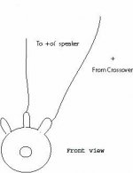

Ok then let me try to explain the way I have it wired.With looking at the Variable Resistor from the front with the shaft facing forward there are 3 posts for connecting the wires too.The one one the right(3rd post) I have the lead from the crossover ( + ) to this post.The middle post I have a lead going to the ( + ) of the speaker.The Left post ( 1st) is left empty as I have the ( - ) ground from the crossover direct to the the ( - ) of the speaker.Is this wrong?
That is how I suspected you had wired it. The way Sreten has suggested wiring it up you end up with one resistance in series with the tweeter and one in parrallel, and provided the required series resistance isn't too high then I guess that the ratio will approximate that of a real L-PAD (is that correct Sreten?).....
eg if you have a 16 ohm pot as Sreten suggested, and you have 2 Ohm's in series then you will have 14 Ohms in parallel which is pretty close to what the formulars say you should use.
Think of the variable resistor as a long strip, the pins on the left and right are each end of the resistor and the middle pin is a tap which can move anywhere along the strip, if the total is 16 Ohms, then at any point on the strip you will have a particular resistance from left to middle and the resistance from right to middle will be 16 - the resistance from left to middle. so if the resistance from left to middle is 4 ohms the resistance from right to middle will be 12 ohms. When you turn the knob you are moving that center tap (wiper) along the strip.
Regards,
Tony.
That depends on the value of your pot! If its 16 Ohms I'd say do as Sreten suggested. If you think it's better keep it that way, if you prefer it the way you had it, change it back.
If the pot is a different value though then wiring the way Sreten suggested probably wont work properly as the ratio will be wrong.
You probably need to do some reading on basic electronics 🙂 will help a lot..... Ohms law would be a good starting point....
Regards,
Tony.
edit: Hmmmm........ I just tried drawing it and I think I have mis-interpreted what Sreten said, best wait for him to reply!
OK temporary brain failure has subsided, see attached image, hopefully that clears things up. Sorry about the roughness 🙂 Well almost, I obviously can't spell resistor!
Attachments
- Status
- Not open for further replies.
- Home
- Loudspeakers
- Multi-Way
- Tweeter Help