so i am running bowers and wilkins lcr600 s3. these are 2.5 way speakers. 2 identical woofers and one tweeter.
one woofer plays mid range.
second woofer plays mid range and bass.
cross over points are 300hz and 4000hz
i found these to be the best from 600 series. bookshelf size.. and overall pretty balanced.
what i would like is to separate or boost mid frequencies a bit. they sound kind of muddied up. nothing horrible.
i've read about cross overs a little. at this point its a long journey to learn all nuances and details.
so i am thinking of converting this 2.5 cross over into a 3 way cross over
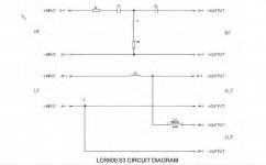
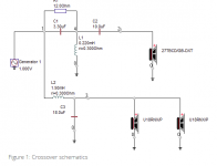
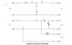
attached is cross over diagram.
C1 4u7 (this is exactly how it's written in service manual) and 100V polyester
C2 is 10uF 100V polyester
r1 is 0k47 7W
r2 is 1k8 7W
L1 .07mH .45mm wire
l2 .7mH .9mm wire air bobbin
l3 5mH .09 wire wicon
they also have DM604 s3 speakers which are 3 way. ill post specs in the next post. i was thinking of using those cross overs on lcr600 s3.
i've done cross over recap before. excellent manual dexterity.
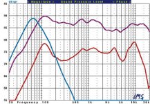
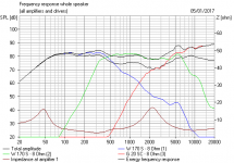
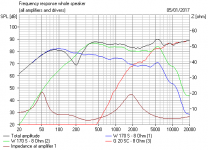
edit: also attaching frequency response sourse (The $3,000 Speaker Derby B&W | Sound & Vision)
purple trace(highest db values across frequencies)
woofer resistance in 600 series is 3.6-3.7 ohm if i remember correctly. measured a few. total speaker impedance 8ohm
one woofer plays mid range.
second woofer plays mid range and bass.
cross over points are 300hz and 4000hz
i found these to be the best from 600 series. bookshelf size.. and overall pretty balanced.
what i would like is to separate or boost mid frequencies a bit. they sound kind of muddied up. nothing horrible.
i've read about cross overs a little. at this point its a long journey to learn all nuances and details.
so i am thinking of converting this 2.5 cross over into a 3 way cross over
attached is cross over diagram.
C1 4u7 (this is exactly how it's written in service manual) and 100V polyester
C2 is 10uF 100V polyester
r1 is 0k47 7W
r2 is 1k8 7W
L1 .07mH .45mm wire
l2 .7mH .9mm wire air bobbin
l3 5mH .09 wire wicon
they also have DM604 s3 speakers which are 3 way. ill post specs in the next post. i was thinking of using those cross overs on lcr600 s3.
i've done cross over recap before. excellent manual dexterity.
edit: also attaching frequency response sourse (The $3,000 Speaker Derby B&W | Sound & Vision)
purple trace(highest db values across frequencies)
woofer resistance in 600 series is 3.6-3.7 ohm if i remember correctly. measured a few. total speaker impedance 8ohm
Attachments
Last edited:
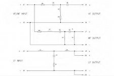
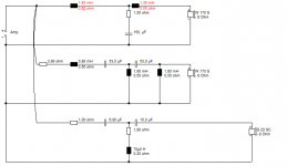
this is DM604 s3 diagram.
these speakers use larger woofers 8" i believe. tweeter is the same. LCR600 is magnetically shielded tweeter and sounds much smoother than 604 s3 tweeter.
R1 1R 11W
R2 3R9 11W
R3 1R 7W
r4 1R8 7W
need to call BW to get ohm values i guess. these look like secret codes to me
c1 150uF 100V
c2 53uF 100V
c3 53uF 100V
c4 6u8 100v
c5 10uF 100V
L1 1.8mh
l2 1.3mH
L3 .8mH
L4 1.8mH
L5 1.8mH
L6 .07mH
Attachments
Hi Richard,
First, do the basics. Move speakers away from walls and/or plug bass ports if any with socks.
I just looked online and I found a measurement from S&V which shows a broad depression from around 2 kHz up until 6 kHz:
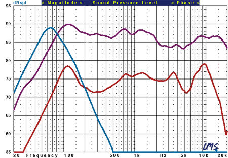
If this is fixable it will require a crossover re-think. How do you feel about equalizing instead? It would be your fastest, most reliable solution.
While I'm probably known for suggesting part upgrades, I would hold off in your case. You could make them sound better, but not well I think unless you take a more holistic approach, which is essentially crossover re-design. May be worthwhile to see if anyone else has attempted this.
Best,
Erik
First, do the basics. Move speakers away from walls and/or plug bass ports if any with socks.
I just looked online and I found a measurement from S&V which shows a broad depression from around 2 kHz up until 6 kHz:
If this is fixable it will require a crossover re-think. How do you feel about equalizing instead? It would be your fastest, most reliable solution.
While I'm probably known for suggesting part upgrades, I would hold off in your case. You could make them sound better, but not well I think unless you take a more holistic approach, which is essentially crossover re-design. May be worthwhile to see if anyone else has attempted this.
Best,
Erik
but LCR600 diagram looks so simple) i don't need to touch tweeter section. just stop sending 300-4000hz to one of the woofers. and installing a little switch that will turn the speaker from stock configuration to 3 way.
i've heard unwinding coils can shift dB from lower to midrange.
i've heard unwinding coils can shift dB from lower to midrange.
confusing. from what i read induction coil act as low pass filter. so L2 removes 4k hz frequencies and above
L3 removes 300 hz frequencies and above.
this looks like a tweeter + bass and midrange(0-4k hz) + bass (0-300hz) as opposed to
tweeter + bass and midrange(0-4k) +pure midrange(300-4khz)
am i reading this diagram right?
L3 removes 300 hz frequencies and above.
this looks like a tweeter + bass and midrange(0-4k hz) + bass (0-300hz) as opposed to
tweeter + bass and midrange(0-4k) +pure midrange(300-4khz)
am i reading this diagram right?
Attachments

Last edited:
I just ran this simplistic 2.5 design up the flagpole with 6" paper drivers.
It relies on the natural rolloff of the kevlar basses. Must have heavy bass too, as is natural with a 2.5 way.
I wouldn't mess with it. Honestly. You could redesign it as an MTM, but that would be a wildly different animal. And I really couldn't guess the frequency response of the bass units. Though I'd guess you hear some breakup from them around 5kHz.
Attachments
wow thanks) i was just confused with 2.5 marketing . i've read somewhere it's bass/midrange + pure midrange + tweeter.
but looking at LCR600 diagram it looks like bass + bass/midrange + tweeter.
yes bass is on the heavier side..
i don't think i should do any major mods.. but i was thinking of integrating a simple high pass filter which can be turned on or off with a button. basically integrate a capacitor in series and induction coil in parallel with ULF speaker.
i understand it's hard to do anything without any info about speakers. but looking at high pass filter on dm604 s3 midrange..
maybe go with
L4 1.8mH
c2 53uF 100V
this may cut lower frequencies below 450hz.. or look at other 600 series cross overs at their high pass filter. ideally id like midrange to play around 300hz and up
this way ill have a dedicated midrange.
Last edited:
The world is your oyster with a redesign, but you'd want to model it a bit first.
You'll lose bass with some sort of highpass to the mid.
The SEAS Bragi is a competent simplistic MTM:
BRAGI
But getting to the same place with your speaker involves rather more guesswork than I am comfortable with.
You'll lose bass with some sort of highpass to the mid.
The SEAS Bragi is a competent simplistic MTM:
BRAGI
But getting to the same place with your speaker involves rather more guesswork than I am comfortable with.
Attachments
i was thinking of MTM. but definitelly need some extension to the subwoofer. i may not do this project. but just wanted to see if it's a simple experiment that may help.
i do want to lose some bass. and gain a bit of midrange.
parts express here sells these 300hz high pass filters.
300 Hz High Pass 4 Ohm Crossover
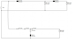
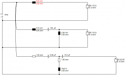
attached is the drawing of what i am planning to do. woofers are around 3.7-4ohm. i am thinking of inductor of around 2mH. capacitor of 100uf. i followed parts express recomendations which are a bit confusing. there is no C1 recomendation for 300hz first order high pass filter.
Resources - Crossover Component Selection Guide
i do want to lose some bass. and gain a bit of midrange.
parts express here sells these 300hz high pass filters.
300 Hz High Pass 4 Ohm Crossover
attached is the drawing of what i am planning to do. woofers are around 3.7-4ohm. i am thinking of inductor of around 2mH. capacitor of 100uf. i followed parts express recomendations which are a bit confusing. there is no C1 recomendation for 300hz first order high pass filter.
Resources - Crossover Component Selection Guide
Attachments
Last edited:
Alas, that 100uF and 2mH doesn't work at all, my friend. It's just a mess when I model it. Downloads
I did try the DM604 s3 filter with something resembling your drivers. The idea has the potential to work IMO. But you will need a separate mid enclosure.
IF the mid and tweeter drivers are the same in the DM604 s3, you need only modify the bass section for some sort of result. This is not hard, but remember the 604 has twin basses. Which probably means you must attenuate the mid and tweeter somewhat. It certainly is less efficient after the mod.
Attachments
hm. i really appreciate your patience with me). of course capacitor and inductor values were chosen half random)
but how can things go wrong if you just cut lower frequencies with 300hz high pass filter for 4ohm woofer..
like this one:
300 Hz High Pass 4 Ohm Crossover
i am just trying to understand) both woofers are identical.
but how can things go wrong if you just cut lower frequencies with 300hz high pass filter for 4ohm woofer..
like this one:
300 Hz High Pass 4 Ohm Crossover
i am just trying to understand) both woofers are identical.
The reason it doesn't work, is you have a 0.7mH coil in series. This turns the 100uF/2mH into a bandpass filter with a horrible notch.
You really have to use a modelling program. BTW, you can import any of these projects into Boxsim projekte folder, and then modify them to your hearts content. If you start with a similar project and drivers, it can all be done quite rapidly.
https://boxsim-db.de/kategorie/systeme/drei-wege/
People throw their hands up in horror when I substitute disimilar drivers, but I just like to get a feel for how it works, without worrying about detail. Impedance is fairly indifferent to the exact driver used, for instance. And you want that above 4 ohms and as flat as possible.
You have to be careful here. These kevlar drivers must be around 6 ohms dc resistance, which is 8 ohms nominal, or impedance would go ridiculously low wired in parallel.
You need to measure the individual drivers to be sure.
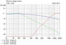
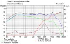
Here's how the filter looked. Horrible. Phase gone haywire. Impedance is too low, as well.
You need to measure the individual drivers to be sure.
Here's how the filter looked. Horrible. Phase gone haywire. Impedance is too low, as well.
Attachments
I couldn't really get anything simple that worked.
I did quite like the idea of wiring the basses in parallel with a 1.2mH coil in front.
MTM. But it's tonally different. And it doesn't address the 5kHz kevlar cone breakup, which must be there. And would get worse if you lifted the midrange.
Edit. Could be worth a try just shorting out the 5mH coil. Leave the 0.7mH in place.
Last edited:
All 6" cones have a 4-6kHz resonance which comes from the sound bouncing back from the surround. You can always see it in the phase response, which means stored energy.
Kevlar traditionally breaks up spectacularly and badly. Much worse than, say, polycones. I don't know how clever B&W are in their designs, but I think the problem must be lurking there.
Shorting out that 5mH coil takes the impedance a little lower around 4 ohms in the midrange area, but not dangerously so if these are 8 ohm drivers.
It lifts the midrange a bit, and reduces the bass a little. A cheap experiment. You can use 15A/30A fusewire to solder the gap.
Last edited:
as far as impedance.. i believe i once measured impedance of each driver with ohm meter. i remember tweeter was 2.9-3.2ohm.. woofers i cant remember. is this the proper way to measure resistance of drivers. i have yamaha mx1.. it's supposed to handle 2ohm loads rms. not dynimic 2ohm load.
but speakers are definitely 8ohm.
but speakers are definitely 8ohm.
An ohmmeter on the low resistance scale ought to work well enough. But amplifiers are expensive to replace, so I am cautious with modifications unless I know exactly what I am dealing with.
So were hoping we have two 8 ohm basses in parallel, making a comfortable 4 ohm load.
I did suspect that B&W tweeters are low resistance, the filters always look like 4 ohm ones.
So were hoping we have two 8 ohm basses in parallel, making a comfortable 4 ohm load.
I did suspect that B&W tweeters are low resistance, the filters always look like 4 ohm ones.
- Status
- This old topic is closed. If you want to reopen this topic, contact a moderator using the "Report Post" button.
- Home
- Loudspeakers
- Multi-Way
- tweaking / light touch up/ mod of BW LCR600 s3 speakers