Hi,
I'm in the decision making fase of building a new pair of speakers. What I'm sure of is that it will be a 'PA' style two-way with a 15" woofer and a horn loaded top. What's also a given is that it's going to be a proven design as I'm not a speaker designer, I just love building them and love woodworking.
I've selected a couple of candidates and they al have the same 'problem': too deep and plain rectangular boxes.
The changes I'm thinking of making are aimed purely at looks and a more challenging build. If that would result in sound improvements, great. It should not change the way the speaker sounds in a major way.
From what I've read, the shape of the box doesn't have a major effect on the performance if you keep the baffle and internal volume the same.
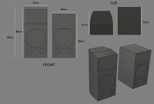
So, looking at the attached mockup, would making the baffle 10cm higher and moving the horn up by 10cm have any serious effect on sound?
The width vs depth is also closer to a 1:1 ratio (1:1.05) which is bad I read. Does curving the sides help with this or should it really be at least 1:1.2 ?
The rectangular box in the attachment is the original design, the higher, curved box is my 'design'
Thanks
I'm in the decision making fase of building a new pair of speakers. What I'm sure of is that it will be a 'PA' style two-way with a 15" woofer and a horn loaded top. What's also a given is that it's going to be a proven design as I'm not a speaker designer, I just love building them and love woodworking.
I've selected a couple of candidates and they al have the same 'problem': too deep and plain rectangular boxes.
The changes I'm thinking of making are aimed purely at looks and a more challenging build. If that would result in sound improvements, great. It should not change the way the speaker sounds in a major way.
From what I've read, the shape of the box doesn't have a major effect on the performance if you keep the baffle and internal volume the same.
So, looking at the attached mockup, would making the baffle 10cm higher and moving the horn up by 10cm have any serious effect on sound?
The width vs depth is also closer to a 1:1 ratio (1:1.05) which is bad I read. Does curving the sides help with this or should it really be at least 1:1.2 ?
The rectangular box in the attachment is the original design, the higher, curved box is my 'design'
Thanks
Attachments

As long as the internal volumes are the same I doubt you would have any problems. If it was my project I'd be more worried about flushing the driver and horn into the baffle and having some form of roundover on the edges.
What's the horn on the speaker ? Looks a lot like my old JBL's..
Cheers,
Rob
What's the horn on the speaker ? Looks a lot like my old JBL's..
Cheers,
Rob
My vote is always 1000% sound over form...
Hey, what would you want if you were blind?
I want to maximize enjoyment from each of our sensory perceptions...
so i vote to give each sense its maximal best vehicle for that, without compromise to the others...
IOW, screw how audio looks!
hang some dang art on the wall 😀
Hey, what would you want if you were blind?
I want to maximize enjoyment from each of our sensory perceptions...
so i vote to give each sense its maximal best vehicle for that, without compromise to the others...
IOW, screw how audio looks!
hang some dang art on the wall 😀
Let me start by saying I'm not a speaker designer, so this is merely an unsubstantiated personal opinion!So, looking at the attached mockup, would making the baffle 10cm higher and moving the horn up by 10cm have any serious effect on sound?
The width vs depth is also closer to a 1:1 ratio (1:1.05) which is bad I read. Does curving the sides help with this?
The horizontal orientation of the horn gives good vertical dispersion, so moving the horn 10cm upwards should not unduly affect the driver integration.
The curved design will help break up internal standing waves in a similar way to using a 'golden ratio' for the enclosure dimensions, so this is unlikely to upset the enclosure performance substantially.
Now wait for the experts to shoot me down in flames! 😀
I'm all for form follows function, that's one of the reasons I started this thread. If I'm likely to mess up the sound, I'll either build it the way it was designed or find another design.
I'm just curious how sensitive a cabinet + crossover is to changes. Can I move a driver position by 1cm, or 5, or 20? I don't know.
I'm not only in it for looks, I also want something that keeps me busy until we all can finally get out of the house and get some **** drinks 🙂
I'm just curious how sensitive a cabinet + crossover is to changes. Can I move a driver position by 1cm, or 5, or 20? I don't know.
I'm not only in it for looks, I also want something that keeps me busy until we all can finally get out of the house and get some **** drinks 🙂
So, looking at the attached mockup, would making the baffle 10cm higher and moving the horn up by 10cm have any serious effect on sound?
The horizontal orientation of the horn gives good vertical dispersion, so moving the horn 10cm upwards should not unduly affect the driver integration.
The crossover has been designed to work with the horn and woofer in that position, moving the horn relative to the woofer will cause a change and the crossover is unlikely to work as well as it was originally designed.
If you can't or don't want to rework the crossover keep the relative distances the same.
Likewise flush mounting the horn or woofer would need to keep the same relative z distance from each other.
Eliminate the base and add to the bottom. Leave the ports where they're at.
Are those the Calpamos?
Are those the Calpamos?
Last edited:
Yes, they are the Calpamos from Humble homemade hifi. Horn is the P-Audio PH-2380. Woofer is the Faital Pro 15PR400.
I added the picture because this design is high on my list but my question is more a general one. I'm wondering how much freedom you have in changing cabinet shapes and volume. Is it all super tightly specced, or can you take it more like guidelines like with tubes and voltages: if you stay within say 5-10% of the original dimensions, you're fine
I added the picture because this design is high on my list but my question is more a general one. I'm wondering how much freedom you have in changing cabinet shapes and volume. Is it all super tightly specced, or can you take it more like guidelines like with tubes and voltages: if you stay within say 5-10% of the original dimensions, you're fine
Hi,
I'm in the decision making fase of building a new pair of speakers. What I'm sure of is that it will be a 'PA' style two-way with a 15" woofer and a horn loaded top. What's also a given is that it's going to be a proven design as I'm not a speaker designer, I just love building them and love woodworking.
I've selected a couple of candidates and they al have the same 'problem': too deep and plain rectangular boxes.
The changes I'm thinking of making are aimed purely at looks and a more challenging build. If that would result in sound improvements, great. It should not change the way the speaker sounds in a major way.
From what I've read, the shape of the box doesn't have a major effect on the performance if you keep the baffle and internal volume the same.
So, looking at the attached mockup, would making the baffle 10cm higher and moving the horn up by 10cm have any serious effect on sound?
The width vs depth is also closer to a 1:1 ratio (1:1.05) which is bad I read. Does curving the sides help with this or should it really be at least 1:1.2 ?
The rectangular box in the attachment is the original design, the higher, curved box is my 'design'
Thanks
Hi, in keeping with the original baffle, the baffle has to stay exactly as is. You cannot move the drivers away from each other. The transition frequency from bass to mid/treble is controlled in the crossover at a certain frequency where the distance between the center of the drivers are one important parameter.
If you prolong the baffle below the drivers, that will have limited effect, but moving the drivers more apart is not a good idea. That will effect the vertical dispersion in a negative way, causing dips and peaks in the dispersion which will be reflected by the ceiling/floor. You can probably move the drivers closer to each other compared with the original baffle if there is room for that.
Last edited:
Generally speaking, a 5 to 10% change in dimensions won't have much of a deleterious effect as the diffraction changes are likely to be less than 1dB. Sometimes it might even help things. Download a baffle diffraction simulator like the Edge which is free and pretty easy to use, input the changes you are thinking off and see for yourself what happens to the baffle diffraction response.
But as others have noted, it's better if you keep the same physical relationships at the top of the speaker and between the drivers as the original design. So simply add the extra height to the bottom of the speaker instead of at the top. There will be virtually no change in response under those conditions.
Also generally speaking, cabinet dimensions that produce a 1:1 ratio are not a good idea because both dimensions will both produce standing waves at the same frequency. Note however that that is only a problem if the driver is actually producing that specific frequency. So for eg., you'll see that a cube shaped subwoofer is perfectly acceptable if the standing wave frequency is above the sub rolloff frequency.
But even if the standing waves are within the passband of the woofer (an internal wavelength of about 37cm equates to a frequency of about 931Hz), it's a problem that is easily overcome with the addition of internal bracing and/or partitioning that will alter the ratio of the internal dimensions. So in other words, if your width and depth are both about 45cm, just put in some vertical bracing from top to bottom, best done with slightly different distances between braces. For a 45cm wide cabinet, I'd probably put in 2 vertical braces, breaking up the internal width into something like 10cm, 12cm and 14cm sections if you are working with 20mm thick wood. Some horizontal braces front to back would be a good idea too. To help prevent standing waves occurring through the holes/cutouts in the bracing, alternate where the holes/cutouts are located in opposite braces.
Note also that if you break up the internal dimensions into smaller units, any standing waves that might happen to still form between braces will be higher in frequency and higher frequencies are always easier to absorb with a little stuffing/insulation in the middle of the cavity.
^ Sorry, but anything one can fit inside a box are acoustically too small to have an effect for the box dimension related standing waves. One would have to make a brace as big as a wall, but they introduce even longer path to have lower standing waves, which is kind of worse (if there is a problem, it is easier to dampen highs than lows, because the wavelenghts are shorter!). Maybe bracing have a little effect to higher modes but stuffing can handle those. The bracing is to stiffen the panels, optimize bracing for that. If there is problem with the standing waves, one could build a resonator of sorts. Stuffing is usually enough. One can put the driver to acoustical center to kill the lowest mode(s).
As always there are compromises to choose from and a good loudspeaker wizard would know exactly what they are so bracing as well as other aspects of an enclosure must have a purpose, don't mistakenly use bracing for internal standing waves, use them for stiffening. Hence my writing, an advice and reminder of the all encompasing yingyang. Have fun! 🙂
As always there are compromises to choose from and a good loudspeaker wizard would know exactly what they are so bracing as well as other aspects of an enclosure must have a purpose, don't mistakenly use bracing for internal standing waves, use them for stiffening. Hence my writing, an advice and reminder of the all encompasing yingyang. Have fun! 🙂
Last edited:
All very welcome and helpful comments
Do curved sides do anything for standing waves or do they serve another purpose?
Do curved sides do anything for standing waves or do they serve another purpose?
The curved sides may have more of an in-room effect than in-box, me thinks.
Looking at the original enclosure, a guy could do a bit to improve the front baffle as far as driver/horn fit. If you rear mount the drivers and flush up the baffle/sides you can do a nice edge treatment. You could also blend the horn mouth in to the sides as well.
The woofer is a good one. According to Winisd, a box a bit over 115l tuned to 35hz will still give decent bass response (-6db@40hz). The original 180l enclosure goes about 10hz lower. Don't know where your at with your design but this will give you a rough idea about bass extension.
If you add to the bottom, maybe you could fabricate a resonance trap there. Like a flat spiral with absorption. Entrance to the spiral would be through a faux bottom corner. You'd still be adding the volume and the spiral might help kill some box noise.
^ Sorry, but anything one can fit inside a box are acoustically too small to have an effect for the box dimension related standing waves. One would have to make a brace as big as a wall, but they introduce even longer path to have lower standing waves
I'm having a hard time understanding how it's possible to introduce a longer distance between parallel reflecting surfaces inside a cabinet by using bracing within that same cabinet. Perhaps you could explain in a little more detail.
For the OP, I should perhaps correct myself. I had thought that the frequency of standing waves corresponds to the distance between reflecting surfaces but this is incorrect. Instead, the distance between surfaces is equivalent to only half the wavelength of the standing wave. This means the frequency of the standing wave is even lower than I thought.
So as an eg., if the distance between parallel reflecting surfaces is 20cm, instead of the standing wave being about 1520Hz, it will be closer to about 860Hz. See here for more detail.
Interestingly, the woofer in that speaker is being rolled off at about 700Hz, so if you could reduce the distance between all parallel reflecting surfaces to less than somewhere around 20cm (standing wave frequency ~=860Hz), then there would be no standing waves generated inside the cabinet because that frequency is not being produced inside the cabinet.
Also in terms of standing waves, the front to back dimensions are supposed to be the most important. But if you look at the speaker you have chosen, the front baffle is almost completely composed of a very large woofer and a very large waveguide (ie. predominantly surfaces that are not parallel to the back panel). In other words, there is actually very, very little parallel surface area for sound to be reflected back and forth between the back panel and the front, the necessary conditions to form standing waves. So the standing waves you need to be most concerned with with that cabinet are top to bottom and side to side.
jReave, a substantial brace (that is attached to three panels) would make "a fold", think folded transmission line speakers. Even this kind of "brace" leaves a path between the parallel walls and the standing wave remains and in addition to that there is now even longer path around the brace/fold.
The lowest modes are the most problematic and thus the main enclosure dimensions define the best case (highest achievable lowest modes 🙂. Anyway, bracing is to stiffen the enclosure and standing waves can be addressed with box dimensions, stuffing, woofer position and even with resonators if need be. 2 way speakers are more difficult than 3 way speakers in this regard.
The lowest modes are the most problematic and thus the main enclosure dimensions define the best case (highest achievable lowest modes 🙂. Anyway, bracing is to stiffen the enclosure and standing waves can be addressed with box dimensions, stuffing, woofer position and even with resonators if need be. 2 way speakers are more difficult than 3 way speakers in this regard.
I might point out that the Peavey SP2-G which reports 54-17 khz +- 3 db and 2nd harmonic distortion 20 db down @ 1m 1w, has a trapezoidal case similar to the 2nd one in post 1. The front is wider than the back. This is a 15" woofer with 2" driven horn with internal crossover. (biamp connectors are available).
The sides are not curved, however.
I liked the sound of my SP2-XTs a lot. The burglar liked them so much he carted them off to his fence. Burglar took all pro electronics, but left everything home built. So I'm thinking of building two SP2-XT. Very ugly, unpainted. I have scored a used 22XT driven plastic horn, and a 22T driven plastic horn. I don't have a car anymore to buy used SP2s, and renting a car to drive 500 mi RT to buy the ones on ebay adds $250-300 to the cost: Of speakers that attract thieves that look in through the window. Probably they wouldn't fit in a compact rental car. Lowes will deliver MDF sheets for $65. At this point crossover design and box internal design is a big mystery. The SP2-XT were sealed.
Last edited:
tmuikku, thanks for the reply but sorry, I'm still not getting it.
First let's make sure we agree on the definition of standing waves. Standing waves form when a soundwave is reflected back and forth between 2 parallel surfaces such that each reflected wave is a mirror image of the other and the wavelength of the standing wave will be equal to twice the wavelength of the reflected wave.
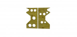
Now in case we are each thinking of a different bracing situation, attached is a very simple rendering of the cabinet in question with 2 vertical braces as I suggested in my original post. The 2nd pic shows only the braces from the side with the intent to highlight that the breathing holes in each brace are offset, or in other words that they do not line up in the vertical dimension and therefore will not allow a straight path from 1 side of the cabinet to the other.
Now clearly as you say there are still pathways for sound to travel between the braces and the parallel sides. No question there. However the only places that allow a direct path for reflections to form between the side panels should be the tiny spaces between the driver cutouts and the drivers (in the tweeter's case, the waveguide also) pic 1, top arrow. Otherwise, the side to side reflections and therefore the horizontal standing waves now should only exist between each side wall and the surfaces of each brace including through each hole in 1 brace to the surface of the next brace (middle arrows), as well as between the parallel surfaces between each brace (bottom arrow). Pic 1 doesn't include any horizontal braces but I would add some of those in as well. One could also take it a step further and install the braces at angles so there would be virtually no parallel surfaces at all.
I'm also having a hard time understanding your difficulty accepting the idea that something can perform more than 1 function. Yes, the primary function of bracing should be to solve panel resonance problems but as a secondary function they can also break up the formation of standing waves. Damping material will also most certainly help to prevent the formation of standing waves, but it will also help prevent reflected sound from leaking back through the driver cones, help to diminish the sound transmission through panel walls and thereby also help to attenuate the amplitude of panel vibrations, as well as function to alter the internal volume that a driver will see. Multiple functions in other words.
The same can be said for xo components. A single series inductor can function to compensate for baffle step loss, help to determine the driver roll-off at the xo frequency and with the addition of a parallel capacitor, it can also function to create a deep notch. Designing with something that performs multiple functions just seems like good engineering to me.
If any of the above is incorrect, please let me know.
First let's make sure we agree on the definition of standing waves. Standing waves form when a soundwave is reflected back and forth between 2 parallel surfaces such that each reflected wave is a mirror image of the other and the wavelength of the standing wave will be equal to twice the wavelength of the reflected wave.
Now in case we are each thinking of a different bracing situation, attached is a very simple rendering of the cabinet in question with 2 vertical braces as I suggested in my original post. The 2nd pic shows only the braces from the side with the intent to highlight that the breathing holes in each brace are offset, or in other words that they do not line up in the vertical dimension and therefore will not allow a straight path from 1 side of the cabinet to the other.
Now clearly as you say there are still pathways for sound to travel between the braces and the parallel sides. No question there. However the only places that allow a direct path for reflections to form between the side panels should be the tiny spaces between the driver cutouts and the drivers (in the tweeter's case, the waveguide also) pic 1, top arrow. Otherwise, the side to side reflections and therefore the horizontal standing waves now should only exist between each side wall and the surfaces of each brace including through each hole in 1 brace to the surface of the next brace (middle arrows), as well as between the parallel surfaces between each brace (bottom arrow). Pic 1 doesn't include any horizontal braces but I would add some of those in as well. One could also take it a step further and install the braces at angles so there would be virtually no parallel surfaces at all.
I'm also having a hard time understanding your difficulty accepting the idea that something can perform more than 1 function. Yes, the primary function of bracing should be to solve panel resonance problems but as a secondary function they can also break up the formation of standing waves. Damping material will also most certainly help to prevent the formation of standing waves, but it will also help prevent reflected sound from leaking back through the driver cones, help to diminish the sound transmission through panel walls and thereby also help to attenuate the amplitude of panel vibrations, as well as function to alter the internal volume that a driver will see. Multiple functions in other words.
The same can be said for xo components. A single series inductor can function to compensate for baffle step loss, help to determine the driver roll-off at the xo frequency and with the addition of a parallel capacitor, it can also function to create a deep notch. Designing with something that performs multiple functions just seems like good engineering to me.
If any of the above is incorrect, please let me know.
Attachments

jReave, thanks for the images. To me, this sounds like a very logical solution to a cabinet that might be susceptible to standing waves due to its dimensions (square-ish). Would be interesting what others think, as I'm not very well educated in the science of acoustics.
Following this logic, wouldn't diagonal braces be even better?
Following this logic, wouldn't diagonal braces be even better?
- Home
- Loudspeakers
- Multi-Way
- Tweaking cabinet shape - form over function or acceptable?