Twiddle sticks are pretty essential for adjusting dust cores tbh.
Some of mine from an old thread. Not shown are the 'phossies' the non ferocious (non ferrous) phosphor bronze double ended trimmers that were an essential part of any service kit back in the day.
Matchsticks and bits of old plastic shaved down can be effective in some cases.

Some of mine from an old thread. Not shown are the 'phossies' the non ferocious (non ferrous) phosphor bronze double ended trimmers that were an essential part of any service kit back in the day.
Matchsticks and bits of old plastic shaved down can be effective in some cases.

There is one kit on Amazon from Philmore with mixed reviews that looks like the one you have on the left. Does it need to end with a flat blade or just the hex shape will do? I think in my case, I would need either 1 or 2. Can someone confirm please by looking at previous picture of T201 I posted?

Looks like these things are getting harder to find and getting more expensive.
https://www.mouser.com/ProductDetail/Coilcraft/37-1409?qs=tx5doIiTu8rxEH2txzkmtA==
https://www.mouser.com/ProductDetail/Coilcraft/37-1409?qs=tx5doIiTu8rxEH2txzkmtA==
The tool from Mouser (Coilcraft) seems to be a bit better than the ones in Philmore kit but I can't find any information about the size for both. The coilcraft datasheet just says "one end is stepped with a hex tip for 1/4-28 cores and a smaller hex tip for 10-32 cores." I need about 1.5 to 2 mm diagonally across the hexagone hole.
Does anyone know what tip size (number) or what kit or tool to order?
Molly, does your beige kit (that looks like Philmore) has one with an hex tip of about 1.5-2mm ?
Does anyone know what tip size (number) or what kit or tool to order?
Molly, does your beige kit (that looks like Philmore) has one with an hex tip of about 1.5-2mm ?
They do look similar but mine are around 25 to 30 yrs old now 😱Molly, does your beige kit (that looks like Philmore) has one with an hex tip of about 1.5-2mm ?
Miraculously, I found a local source for these trimmer tools. I just need to find time to go there now.
As for my lost AM radio, it seems my receiver is getting as old as I am as another transistor has failed (Q401 - 2SC657). And Mooly, it will not make you feel any younger, it seems you helped a user 12 years ago to find a replacement for it (https://www.diyaudio.com/community/threads/replacement-for-2sc657-sony.216954/) ! 🙂
As for my lost AM radio, it seems my receiver is getting as old as I am as another transistor has failed (Q401 - 2SC657). And Mooly, it will not make you feel any younger, it seems you helped a user 12 years ago to find a replacement for it (https://www.diyaudio.com/community/threads/replacement-for-2sc657-sony.216954/) ! 🙂
No luck with the tools. The kit I got had 1.8mm Hex and 2.4 Hex. The 1.8 one is too loose and 2.4 does not fit. I will have to order one.
Meanwhile I was working on the lost AM issue and thought I had found a bad transistor but it appears those VHF transistors don't beep with my Fluke in diode mode testing but are working okay.
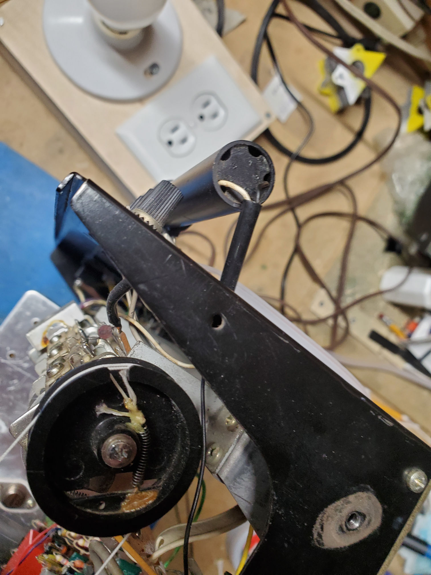
Interestingly, if i put one my of my multimeter lead on the base of Q401, I get reception. Otherwise I don't even get inter-station noise. Q401 is perfectly well soldered and not loose at all. It is almost if my multimeter lead acts an antenna. I checked the am antena but can't find any obvious break. The black and white wire that goes into the tube might be unsoldered? I am posting the picture of the antenna and the voltages for your valuable feedback and recommendations as I don't want to make things worse by opening this antenna:
Notice that voltages are high at the collector of Q402 and Q405, R430 measured 798 ohms:

Meanwhile I was working on the lost AM issue and thought I had found a bad transistor but it appears those VHF transistors don't beep with my Fluke in diode mode testing but are working okay.
Interestingly, if i put one my of my multimeter lead on the base of Q401, I get reception. Otherwise I don't even get inter-station noise. Q401 is perfectly well soldered and not loose at all. It is almost if my multimeter lead acts an antenna. I checked the am antena but can't find any obvious break. The black and white wire that goes into the tube might be unsoldered? I am posting the picture of the antenna and the voltages for your valuable feedback and recommendations as I don't want to make things worse by opening this antenna:
Notice that voltages are high at the collector of Q402 and Q405, R430 measured 798 ohms:
Attachments

I'm still following but its not easy to suggest things without having it in front of you 🙁
Is the oscillator around Q405 running OK with output on C423?
Is the oscillator around Q405 running OK with output on C423?
If adding an 'antenna' to the base of Q401 brings it to life, it is most likely something with the loop antenna and associated caps.
stocktrader200, thanks for pointing out the obvious. I should have thought about doing a continuity test first. Yes, it has continuity.
A scope is on his way. I'm a bit tired to guess with voltages only.
Mooly, what kind of output should I have on C423? I'm measuring 14.85V.
A scope is on his way. I'm a bit tired to guess with voltages only.
Mooly, what kind of output should I have on C423? I'm measuring 14.85V.
You should see the local oscillator signal, a sine wave with a frequency well above the tuned frequency. For example if you tuned to a station transmitting at 1150kHz the oscillator would run at 1150kHz +455kHz (I assume its 455kHz where you are, the UK would be 470kHz, it all depends on the channel spacing in the country concerned).
So you should see a nice clean sine that varies in frequency as you tune and it should be related to the carrier frequency of the transmission by the above figure. When this is mixed with the carrier we get a 'difference' signal which is always at 455kHz (or 470kHz) and this is then passed along for demodulation. The 455kHz is the IF or intermediate frequency and is handled by the following circuitry which is tuned to just that frequency... like an amplifier with a frequency response peaked at 455kHz and very sharp roll off either side of that.
So you should see a nice clean sine that varies in frequency as you tune and it should be related to the carrier frequency of the transmission by the above figure. When this is mixed with the carrier we get a 'difference' signal which is always at 455kHz (or 470kHz) and this is then passed along for demodulation. The 455kHz is the IF or intermediate frequency and is handled by the following circuitry which is tuned to just that frequency... like an amplifier with a frequency response peaked at 455kHz and very sharp roll off either side of that.
Mooly and all of you who keeps helping me and teaching me, you are awesome. I can't never say thank you enough.
As soon as I have my oscilloscope, I will experiment with it and report back.
As soon as I have my oscilloscope, I will experiment with it and report back.
Summer vacations are over and I'm getting back to this. I have acquired a small digital oscilloscope (ZEEWEII DSO3D12) and it is working quite well to see the frequencies in the circuit as explained by Mooly. I also got proper alignment tools and even inherited a Cushman ce-50a monitor but it is not working as the PLL won't lock. This will be another learning project!
AM issue is now resolved. It was a simple connection problem. This yellow wire that you can see in post #49, was disconnected. Looks like it was never soldered in the first place. It stayed in its hole for 50 years until I started messing with the receiver!
To recap the problem, I had made a stereo light with a led and a zener. But FM stereo started to intermittently failed and the signal meter would not move from "0" after a day or two. I then have redone the light circuit with a resistor shunted across as per Mooly's design (see post #12). This did not resolve the intermittent problem and after a few days FM stereo was completely gone. The signal meter is working fine since then.
What I have investigated so far with the help of this forum's users:
Now that I have a scope and a current meter, any suggestions on what else I should check? I have poked around but could not deduct much from the modulated signal.
Thank you all for your valuable help.

AM issue is now resolved. It was a simple connection problem. This yellow wire that you can see in post #49, was disconnected. Looks like it was never soldered in the first place. It stayed in its hole for 50 years until I started messing with the receiver!
To recap the problem, I had made a stereo light with a led and a zener. But FM stereo started to intermittently failed and the signal meter would not move from "0" after a day or two. I then have redone the light circuit with a resistor shunted across as per Mooly's design (see post #12). This did not resolve the intermittent problem and after a few days FM stereo was completely gone. The signal meter is working fine since then.
What I have investigated so far with the help of this forum's users:
- Measured all voltages in the MPX section. See latest readings below.
- Verified that Q301, Q302, Q303 and Q304 are working correctly.
- Documented the functioning of this circuit in post #27
- Checked C314, C316, D301, D302.
- Checked the voltage developed at the junction of D301, D302 when tuned to a strong stereo station. It is between 1.1 and 1.5V. As per Ylli it should be at least 4 volts.
- Shorted C to E on Q303. It brought back the stereo light but did not make it sound stereo.
- Reverted my led circuit to use a bulb of 5V 60mA instead of nominal 4.5V 40mA. Both led and bulb used to work albeit the bulb was quite dim.
- As per Ylli, realigned the FM discriminator by tuning to a strong station and setting T201 to get near zero volts at R238/C215. This is difficult to do without a signal generator as the value changes from station to station. I get now something between 0.05 V to 0.5V depending upon the station. In the process, I did not see the light turned on.
Now that I have a scope and a current meter, any suggestions on what else I should check? I have poked around but could not deduct much from the modulated signal.
Thank you all for your valuable help.
Its hard to pick up from where it left off... its like a zillion posts ago 🙂
Standout voltage on your diagram is the 13.9 on Q303 where it is shown as being 0 for a stereo broadcast. Look with the scope at the junction of R312 and 315 to see if enough voltage is present to turn on Q302. You will need to look at Q302 emitter as a 'reference' to see what voltage would be needed. If we were looking at pure DC it would be approximately two base/emitter volt drops so around 1.2 volts
Standout voltage on your diagram is the 13.9 on Q303 where it is shown as being 0 for a stereo broadcast. Look with the scope at the junction of R312 and 315 to see if enough voltage is present to turn on Q302. You will need to look at Q302 emitter as a 'reference' to see what voltage would be needed. If we were looking at pure DC it would be approximately two base/emitter volt drops so around 1.2 volts
The scope roughly gives me (it varies a bit):
R312-R315 = 0.725 V
Q302e = 0.500 V
Q302b = 0.700 V
I assume you asked me to use a scope because it is filtering AC?
I still have trouble understanding where current flows but are we saying the MPX unit (MU301) is not developing enough voltage as Ylli suggested or are we loosing it somewhere else (what is T301's role for instance)?
You need to see enough voltage at R312/315 to turn on Q302. What you see on at the junction of the resistors will be a partly smoothed full wave rectified 19kHz signal. The scope is the default tool to use for all these voltage measurements because what are are looking at are not simple DC levels but AC signals that in some cases have to have an average level sufficient to turn various transistors on.
There is a very detailed description of all the functions in the first pages of the manual. This and lots more. Have you got the full manual?


There is a very detailed description of all the functions in the first pages of the manual. This and lots more. Have you got the full manual?
Thank you Moly, but when I said I have trouble understanding where current flows I did not mean how the circuit works (I already documented it in post #27) but what makes voltages highers at certain point of the circuit.
For instance, I naively think that because I only have 4.9V instead of 6V at the emitter of Q301, this could be the one volt missing to turn on Q302. But there is the mpx unit that looks like a transformer in between so I assume it is supposed to output the signal to certain amplitude.
At the collector of Q301, the amplitude is 2.38V PkPk:

At the junction of the frequency doubler (D301 and D302), the 38kHz signal is only 250mV:

Do I have a bad M301 or what could make this signal higher?
For instance, I naively think that because I only have 4.9V instead of 6V at the emitter of Q301, this could be the one volt missing to turn on Q302. But there is the mpx unit that looks like a transformer in between so I assume it is supposed to output the signal to certain amplitude.
At the collector of Q301, the amplitude is 2.38V PkPk:
At the junction of the frequency doubler (D301 and D302), the 38kHz signal is only 250mV:
Do I have a bad M301 or what could make this signal higher?
- Home
- Amplifiers
- Solid State
- Tuner meter and stereo signal light on Sony STR-6045