Preprocess Audio to 2 PWM paths
Hi,
yesterday I did it wordy. Today I send a sketch. It is an awful drawing, but is probably near to usable.
I create 2 domains: Semiconductors for high speed circuits on low amplitudes. The other domain is tubed 😀 - including the conversion to high voltage swing OpAmp with 3 symmetrical stages of PCC89 triodes, summing up to 6 tubes PCC89. They drive the GU50 gate 1 between -80V to -50V and something around -5V to -1V ; off or fully open!
Why GU50 ? I have them in stock. And they are powerful, simple pentodes. Quite fast, low g1 capacitance and capable of around 300mA without too much wear.
With 4 of them, I might get around 250W output. A nice side parameter: it sustains 1500V anode voltage, while g1 is at -50V (minimum).
Why PCC89 ? They are very, very fast, normally used in UHF circuits of tube TV. And I have them.
Here is the drawing:
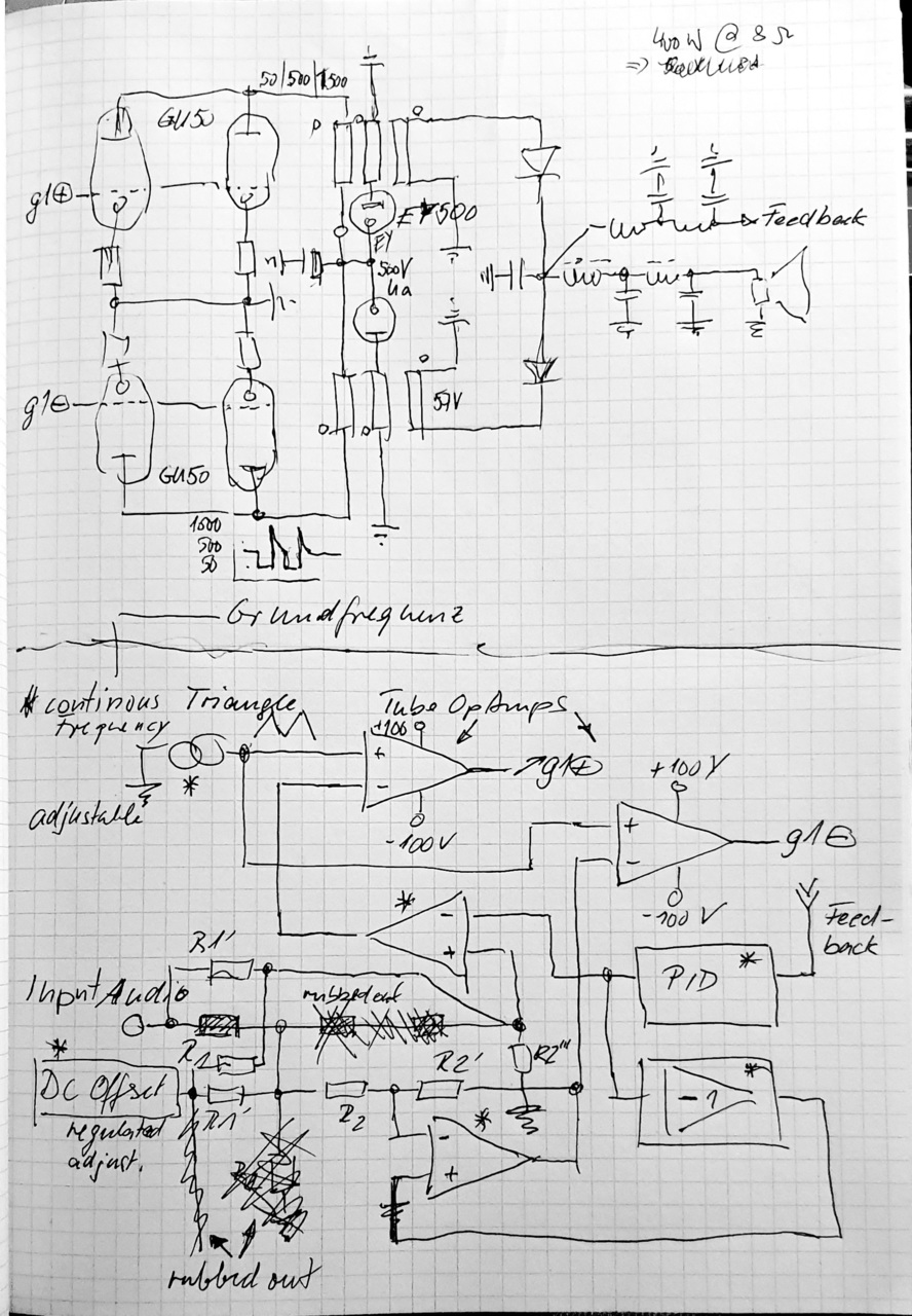
The lower part is new. There are simplified blocks. All parts with a star will be semiconductors. Just in order to avoid months of work and hundreds of bucks. The blocks are PID (proportional, integrated, differential) processing for generating a feedback, which is usable for this powerplant.
In the upper section of lower half, there are 2 opamps, built with symmetrical circuit, drawing from -100V and +100V (might be clipped later). 3 PCC89s will make up 1 opamp.
Wherever I rubbed out parts, you can see my thinking stages...
Finally, there must be some circuit, which makes the entire thing secure, in the sense of: does not destroy itself on powerup or power loss. I will think about that later.
I will use an adjustable triangle; frequency, offset, peak to peak. And I will have another offset, which will cause the 2 powertrains to overlap and make the diode blackout disappear. Most probably, there will be some chokes around to limit RF emission. between the diodes, there might be a double winding choke to catch the overlapping energy. We will see.
Greetings from
Joachim
Hi,
yesterday I did it wordy. Today I send a sketch. It is an awful drawing, but is probably near to usable.
I create 2 domains: Semiconductors for high speed circuits on low amplitudes. The other domain is tubed 😀 - including the conversion to high voltage swing OpAmp with 3 symmetrical stages of PCC89 triodes, summing up to 6 tubes PCC89. They drive the GU50 gate 1 between -80V to -50V and something around -5V to -1V ; off or fully open!
Why GU50 ? I have them in stock. And they are powerful, simple pentodes. Quite fast, low g1 capacitance and capable of around 300mA without too much wear.
With 4 of them, I might get around 250W output. A nice side parameter: it sustains 1500V anode voltage, while g1 is at -50V (minimum).
Why PCC89 ? They are very, very fast, normally used in UHF circuits of tube TV. And I have them.
Here is the drawing:
The lower part is new. There are simplified blocks. All parts with a star will be semiconductors. Just in order to avoid months of work and hundreds of bucks. The blocks are PID (proportional, integrated, differential) processing for generating a feedback, which is usable for this powerplant.
In the upper section of lower half, there are 2 opamps, built with symmetrical circuit, drawing from -100V and +100V (might be clipped later). 3 PCC89s will make up 1 opamp.
Wherever I rubbed out parts, you can see my thinking stages...
Finally, there must be some circuit, which makes the entire thing secure, in the sense of: does not destroy itself on powerup or power loss. I will think about that later.
I will use an adjustable triangle; frequency, offset, peak to peak. And I will have another offset, which will cause the 2 powertrains to overlap and make the diode blackout disappear. Most probably, there will be some chokes around to limit RF emission. between the diodes, there might be a double winding choke to catch the overlapping energy. We will see.
Greetings from
Joachim
Last edited:
Pity you lost your job.- I just wrote for nearly one hour. Then posted.
Stupid short session time did destroy my effort! Text lost, after being asked again to log in! -
Silly, unprofessional.
Also happened to me, many times, since I tend to back what I write with schematics, datasheets, etc.
Oh well.
That said, you can setup your login to never expire, even f you close all Forum windows today and reopen tomorrow, unless logging out on purpose.
Note: Hybrid Class D with 6n6p tubes was a smaller attempt, but the tubes have been just an extension of output stage, from a semiconductor class D amp. It is from 2009 and without pics.
I don't know. It is a shame, these photos are offline in meantime. I can't make me a useful impression.Rube Goldberg?
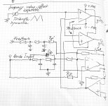
In the meantime I cleared up my awful drawing for gate driving circuits. I place it here again.
It is simplified, technically.
Two aspects: the opamp design and the feedback included signal processing, having the proportional, integrating and differential components included.
For my opinion: better, than before.
It is simplified, technically.
Two aspects: the opamp design and the feedback included signal processing, having the proportional, integrating and differential components included.
For my opinion: better, than before.
Attachments
Last edited:
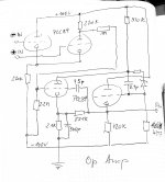
And here the second part, the opamp itself. Simplified and direct related to a well known, proven design, known as philbrick opamp.
Attachments
Last edited:
The right side is single ended. It will drive the the GU50 13pF g1 input. The PCC89 has 10mA drive for a 50V swing. Values are not calculated, nor proven. But a good orientation.
I use a high voltage zener instead of the ionised gas lamps (noise). I lowered voltages to stay within PCC89 specs. Precision will be lower, but speed higher. Which is, what I need. The function is a comparator.
I use a high voltage zener instead of the ionised gas lamps (noise). I lowered voltages to stay within PCC89 specs. Precision will be lower, but speed higher. Which is, what I need. The function is a comparator.
Last edited:
The triangle generator circuit and PID section will be with very fast opamps from AD.
My target is not, to distort the signal in any way. The signal/noise figure shall be very good and the overall feedback is essential.
I will need to remove the lowest frequencies along with DC input - the whole thing would be capable of that! For audio, not the best idea.
My target is not, to distort the signal in any way. The signal/noise figure shall be very good and the overall feedback is essential.
I will need to remove the lowest frequencies along with DC input - the whole thing would be capable of that! For audio, not the best idea.
I comment, can't edit.And here the second part, the opamp itself. Simplified and direct related to a well known, proven design, known as philbrick opamp.
The original Philbrick design was very, very slow. Just because they tried to get high gain, they lowered currents and used high values for resistors. The gain bandwidth product was 100 kHz, which I will improve a lot. The circuit itself will allow this.
Are we talking about Reuben Garrett Lucius Goldberg ? He was type of genius, but not many people recognized his work as art, what is was. My idea is, to proof, while spending lots of work, material, engineering, that tube amps can reach semiconductor performance in terms of noise and distortion - not just sound. I do it, because i can do it.Rube Goldberg?
Result will be properly built, in order to reach my desired level of esthetics.
I feel honored, to play in his league (with tubes) 😊
In the meantime, I got a total of 900 VA of toroid transformers, a very big, high capacity capacitor for my 500V power anode voltage.
I ordered a set of ferroxcube EC 102 cores, for my output transformers. Not easy to get, surprise. But I will start with this 'giant' in order to experiment. Trying to find out, how much energy and frequency I can transfer, while that is far from saturation, far from overheat, keeping efficiency.
That will be fun!
Greetings,
Joachim
Hi, tube enthusiasts,
Today, the ferroxcube EC 102 cores arrived, which shall be heart of the tube class D amp.
Below is a photo, where you can see the dimensions. I am sure, this core is bigger then needed.
But capabilities must be there, while the entire project is of crazy dimensions and art of engineering. The making of, what is possible with tubes, is the target.
These cores are a standard component of electronic converters DC to AC in order to feed the AC lines with solar or wind energy. Swich Mode of course. The cores allow 100 kHz PWM, without significant losses at some 10kW.
The choice was done for easier design, less limits and to keep line at my understanding of technical artwork and beauty.

As size reference, there is a wall plug.
Remember, there will be 2 sets for one channel.
4 tubes GU50 will drive this couple.
Happy christmas,
Joachim
Today, the ferroxcube EC 102 cores arrived, which shall be heart of the tube class D amp.
Below is a photo, where you can see the dimensions. I am sure, this core is bigger then needed.
But capabilities must be there, while the entire project is of crazy dimensions and art of engineering. The making of, what is possible with tubes, is the target.
These cores are a standard component of electronic converters DC to AC in order to feed the AC lines with solar or wind energy. Swich Mode of course. The cores allow 100 kHz PWM, without significant losses at some 10kW.
The choice was done for easier design, less limits and to keep line at my understanding of technical artwork and beauty.
As size reference, there is a wall plug.
Remember, there will be 2 sets for one channel.
4 tubes GU50 will drive this couple.
Happy christmas,
Joachim
Hello ,i see a problem with upper circuit . Lets say upper transformer produces positive voltage through upper diode ,but it will be shorted by another diode and output winding of bottom transformer. You need to design another method for output converting i think .Preprocess Audio to 2 PWM paths
Hi,
yesterday I did it wordy. Today I send a sketch. It is an awful drawing, but is probably near to usable.
I create 2 domains: Semiconductors for high speed circuits on low amplitudes. The other domain is tubed 😀 - including the conversion to high voltage swing OpAmp with 3 symmetrical stages of PCC89 triodes, summing up to 6 tubes PCC89. They drive the GU50 gate 1 between -80V to -50V and something around -5V to -1V ; off or fully open!
Why GU50 ? I have them in stock. And they are powerful, simple pentodes. Quite fast, low g1 capacitance and capable of around 300mA without too much wear.
With 4 of them, I might get around 250W output. A nice side parameter: it sustains 1500V anode voltage, while g1 is at -50V (minimum).
Why PCC89 ? They are very, very fast, normally used in UHF circuits of tube TV. And I have them.
Here is the drawing:
The lower part is new. There are simplified blocks. All parts with a star will be semiconductors. Just in order to avoid months of work and hundreds of bucks. The blocks are PID (proportional, integrated, differential) processing for generating a feedback, which is usable for this powerplant.
In the upper section of lower half, there are 2 opamps, built with symmetrical circuit, drawing from -100V and +100V (might be clipped later). 3 PCC89s will make up 1 opamp.
Wherever I rubbed out parts, you can see my thinking stages...
Finally, there must be some circuit, which makes the entire thing secure, in the sense of: does not destroy itself on powerup or power loss. I will think about that later.
I will use an adjustable triangle; frequency, offset, peak to peak. And I will have another offset, which will cause the 2 powertrains to overlap and make the diode blackout disappear. Most probably, there will be some chokes around to limit RF emission. between the diodes, there might be a double winding choke to catch the overlapping energy. We will see.
Greetings from
Joachim
Hello ximicas,Hello ,i see a problem with upper circuit . Lets say upper transformer produces positive voltage through upper diode ,but it will be shorted by another diode and output winding of bottom transformer. You need to design another method for output converting i think .
I see, what you see. I understand the problem and will invest time to solve that. I am pretty sure to find a way to keep the concept.
Thanks for pointing me to such a basic, simple mistake! I will come up with a solution soon!
Happy christmas,
Joachim
Also i would add that using pwm to drive simple output transformer is used widely ,in ups and dc to ac converter ,whose are marked as Pure sine wave.
12v are pwm'ed through fullbridge mosfets to single winding of upping transformer . But reverse connecting that transformer (trying to use it in power supply in example) gives only about 6,5v AC output ,so its designed differently because switching frequency is higher .But someone wrote earlier that it will not work because of core saturation .But actually its working in practice ,transformer filters out most of high frequency and produces average audio voltage . Linear operation (resistor mode) is replaced by pwm ,when transformer receives some averaged energy . If you want to use tubes for that funny d-class idea ,try that first . Make full bridge of 4 tubes ,or push pull ,use typical output transformer, or try halfbridge and capacitor to separate transformer from possible DC .Also capacitor in parallel to primary winding will make it easier to filter hf harmonics.
12v are pwm'ed through fullbridge mosfets to single winding of upping transformer . But reverse connecting that transformer (trying to use it in power supply in example) gives only about 6,5v AC output ,so its designed differently because switching frequency is higher .But someone wrote earlier that it will not work because of core saturation .But actually its working in practice ,transformer filters out most of high frequency and produces average audio voltage . Linear operation (resistor mode) is replaced by pwm ,when transformer receives some averaged energy . If you want to use tubes for that funny d-class idea ,try that first . Make full bridge of 4 tubes ,or push pull ,use typical output transformer, or try halfbridge and capacitor to separate transformer from possible DC .Also capacitor in parallel to primary winding will make it easier to filter hf harmonics.
Just to clarify: I will do the coil calculations by myself and will do the handcraftet coils.Also i would add that using pwm to drive simple output transformer is used widely ,in ups and dc to ac converter ,whose are marked as Pure sine wave.
12v are pwm'ed through fullbridge mosfets to single winding of upping transformer . But reverse connecting that transformer (trying to use it in power supply in example) gives only about 6,5v AC output ,so its designed differently because switching frequency is higher .But someone wrote earlier that it will not work because of core saturation .But actually its working in practice ,transformer filters out most of high frequency and produces average audio voltage . Linear operation (resistor mode) is replaced by pwm ,when transformer receives some averaged energy . If you want to use tubes for that funny d-class idea ,try that first . Make full bridge of 4 tubes ,or push pull ,use typical output transformer, or try halfbridge and capacitor to separate transformer from possible DC .Also capacitor in parallel to primary winding will make it easier to filter hf harmonics.
The coils, windings will be optimized for low capacitances, low copper losses, minimized eddy currents an best coupling. The RF emission needs a cage for the entire circuit.
Those sine wave circuits and transformers have a low bandwith and lower frequencies.
I feel fool to make this simple mistake and you can expect I will find a solution.
I am grateful, to avoid my hadbanging.
Greetings, enjoy christmas!
Joachim
Curious what would happen if you took a normal class D amplifier and used it to drive a push-pull tube output stage, by driving the cathodes with the amplifier output, with grounded grids?
Many inexpensive class D amps take up to 25V Vcc. Their two outputs sit at Vcc/2 - referenced to ground - such that when a speaker is connected across, it sees 0V until the PWM moves off 50%.
If one chose a tube that biased adequately ~ -12V (6BQ5?) and connected the cathodes to the amplifier output, instead of a cathode resistor, one would think you could set the tube bias simply by changing the Vcc of the class D amp. The amplifier outputs already operate out of phase, for the phase splitter.
Of course there's devil details, such as protecting the amplifier outputs from the tube shorting to HV, how the amplifier will behave with a whole 50mA of current going into the output terminal it's not expecting to see in normal operation. As I understand it, a PWM output stage comprised of a high side and low side FET is pretty low-Z looking into it, source or sink, based on the Rdson of the FETs. So from the POV of the tube's cathode, it's connect to a power supply output. That just happens to move about its quiescent voltage along with an audio signal.
Regarding how that would sound, that depends on what part of a tube amplifier is most responsible for its character. The input pentode? The phase splitter? Or the output tubes, coupling transformer and power supply?
I imagine the class D amp as a phase splitter is going to have perfect symmetry and have no issue at all driving the cathodes of a tube up and down in voltage, over a ~25V p-p cycle, about a 12.5V quiescent. Some class D chips do offer analog feedback from the speaker terminal, which one would think could be arranged from the transformer secondary.
You bet I did ctrl-A, crtl-C before hitting post reply - in case something goes wrong ;')
I'd think this is a nice proposalCurious what would happen if you took a normal class D amplifier and used it to drive a push-pull tube output stage, by driving the cathodes with the amplifier output, with grounded grids?
Many inexpensive class D amps take up to 25V Vcc. Their two outputs sit at Vcc/2 - referenced to ground - such that when a speaker is connected across, it sees 0V until the PWM moves off 50%.
If one chose a tube that biased adequately ~ -12V (6BQ5?) and connected the cathodes to the amplifier output, instead of a cathode resistor, one would think you could set the tube bias simply by changing the Vcc of the class D amp. The amplifier outputs already operate out of phase, for the phase splitter.
Of course there's devil details, such as protecting the amplifier outputs from the tube shorting to HV, how the amplifier will behave with a whole 50mA of current going into the output terminal it's not expecting to see in normal operation. As I understand it, a PWM output stage comprised of a high side and low side FET is pretty low-Z looking into it, source or sink, based on the Rdson of the FETs. So from the POV of the tube's cathode, it's connect to a power supply output. That just happens to move about its quiescent voltage along with an audio signal.
Regarding how that would sound, that depends on what part of a tube amplifier is most responsible for its character. The input pentode? The phase splitter? Or the output tubes, coupling transformer and power supply?
I imagine the class D amp as a phase splitter is going to have perfect symmetry and have no issue at all driving the cathodes of a tube up and down in voltage, over a ~25V p-p cycle, about a 12.5V quiescent. Some class D chips do offer analog feedback from the speaker terminal, which one would think could be arranged from the transformer secondary.
You bet I did ctrl-A, crtl-C before hitting post reply - in case something goes wrong ;')
Hi, interesting concept, but I have one argument against:Curious what would happen if you took a normal class D amplifier and used it to drive a push-pull tube output stage, by driving the cathodes with the amplifier output, with grounded grids?
Many inexpensive class D amps take up to 25V Vcc. Their two outputs sit at Vcc/2 - referenced to ground - such that when a speaker is connected across, it sees 0V until the PWM moves off 50%.
If one chose a tube that biased adequately ~ -12V (6BQ5?) and connected the cathodes to the amplifier output, instead of a cathode resistor, ..... down in voltage, over a ~25V p-p cycle, about a 12.5V quiescent. Some class D chips do offer analog feedback from the speaker terminal, which one would think could be arranged from the transformer secondary.
You bet I did ctrl-A, crtl-C before hitting post reply - in case something goes wrong ;')
High current H bridges have low slew rates. This would degrade the precision and I am afraid the bandwidth of the entire amp would degrade, too.
Tubes as the GU 50 need a 50V swing at g1. This fact already forced me to alter the gate driving circuit.
The charme of your proposal is the simplicity and I expect this can work, if the added phase shift can be respected in the feedback loop.
I personally search for the perfection of bandwith (very, very low frequencies to 20kHz), lowest distortion (by running at high frequencies, very short pulses) and of course:
Tubes as drivers, at finally all stages of all functional groups. But I will start (!) with high performance opamps in the transition from analog to my two PWM generators and feedback processing.
Regarding sound: This is a crucial point. Any class D system, which is based on an existing class D semiconductor amp would be totally dependent on that one's quality.
The 'sound' impact of tubes cannot survive. While I see a well done class D as much better then any tube class AB push pull with pentode g2 feedback out of the transformer.
Analog tube amps will allways be dominated by their output transformer in all aspects.
I want to kill those effects, totally.
The challenge is, to keep a somehow high open loop gain, low phase shift and therefore low dynamic output impedance up to high audio frequencies.
Last edited:
- Home
- Amplifiers
- Class D
- tubes in Class D?