There’s something called Boltzmann noise which relates current, temperature, resistance and noise. Increasing the wattage reduces the heating effect (bigger resistor and can cool itself with more surface area). Another way is to change the value of the resistor and parallel them - for example a 1K resistor can be replaced by two 2K resistors in parallel for the same effect.
Most random noise follows a gaussian distribution over the frequency spectrum so by paralleling you have non similar two noise spectrums but identical signals so the volume of noise increases slower than the signal volume. Thus reducing the noise further.
Most random noise follows a gaussian distribution over the frequency spectrum so by paralleling you have non similar two noise spectrums but identical signals so the volume of noise increases slower than the signal volume. Thus reducing the noise further.
Last edited:

If you’re in Europe, Don Audio has Edcor transformers. Not as cheap as the US, but not as expensive as paying the shipping from the US yourself. Tube-town is also a good place to look for parts. They both also sell Hammond.
https://www.don-audio.com/
https://www.tube-town.net/ttstore/
https://www.don-audio.com/
https://www.tube-town.net/ttstore/
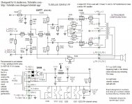
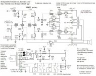
Just thought i'd post the Tubelab SSP schematic along with notes i've come across.
As we known if the Tubelab SPP pcb if to be used, and i'll probably take road now, it's for a stereo build.
i.e. One Mains Transformer and Two output transformers.
May i mention as George has done already in his web site, it is extremely important to read his complete write up about the build.
Can someone enlighten me about http://tubelab.com/designs/tubelab-spp/parts-list/ ?
George writes 3rd paragraph 'The optional parts are covered on the upgrades page'. Can't find that page!
Attachments
IIRC, the major things that George mentioned was that caps 103 and 105 could be upgraded and he suggested not cheaping-out but using decent OPTs right from the start. He suggested Auricaps as a possibility, if memory serves. As far as OPTs go, he wasn't suggesting the purchase of exotic mega-buck trannies, just not selecting too-small transformers that would inhibit power and bass extension. George please correct me if I'm wrong.
One of my builds used Cornell-Dublier 940C caps, the other used Mundorf Supremes, the basic, no fancy metals or oils variety, about 16 USD each. Both the C-Ds and the Mundorfs required some fancy lead bending.
The diodes shown before the rectifier were, I think, a John Broskie recommendation because modern GZ34s are not as rugged as tubes from the valve heyday. There isn't a place for the diodes on the board so you'd have to hack it.
If using the PS choke it actually connects to L1-1 and L1-2.
George, if it's not too impolite to ask, how many SPP boards have you sold? There seems to be a recent rise in SPP interest.
Cheers, Steve
Attachments
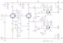
This is a pp the I made time ago with pcb
And the one finished.
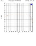
In attach also the frequency answer on 8 ohm 1 watt and same with 0,2uF in parallel
The OT are cistom made, C nucleus. Fedback is around 9 dB
The amp run at around 12 watt rms where the classs A is around the 80 % of total power
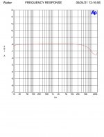
In the last diagram the manitor of the cathode current at 10 wrms on 8 ohm, class A
And the one finished.
In attach also the frequency answer on 8 ohm 1 watt and same with 0,2uF in parallel
The OT are cistom made, C nucleus. Fedback is around 9 dB
The amp run at around 12 watt rms where the classs A is around the 80 % of total power
In the last diagram the manitor of the cathode current at 10 wrms on 8 ohm, class A
Attachments

Thanks Steve, for your valuable reply.IIRC, the major things that George mentioned was that caps 103 and 105 could be upgraded and he suggested not cheaping-out but using decent OPTs right from the start. He suggested Auricaps as a possibility, if memory serves. As far as OPTs go, he wasn't suggesting the purchase of exotic mega-buck trannies, just not selecting too-small transformers that would inhibit power and bass extension. George please correct me if I'm wrong.
One of my builds used Cornell-Dublier 940C caps, the other used Mundorf Supremes, the basic, no fancy metals or oils variety, about 16 USD each. Both the C-Ds and the Mundorfs required some fancy lead bending.
The diodes shown before the rectifier were, I think, a John Broskie recommendation because modern GZ34s are not as rugged as tubes from the valve heyday. There isn't a place for the diodes on the board so you'd have to hack it.
If using the PS choke it actually connects to L1-1 and L1-2.
George, if it's not too impolite to ask, how many SPP boards have you sold? There seems to be a recent rise in SPP interest.
Cheers, Steve
Where is the info about the 'upgrades' ?
As i've mentioned, i would like to try and keep the suppliers as low as possible.
I'm still trying to get my head around all this. I'm far from being a DIY Audio builder and for any build i always start from scratch.
My thoughts are to build the complete Tubelab design, as George has it laid down and spares/valves listed.
But i plan to have all transformers mounted to be viewable and also all the valves viewable too.
Steve (or George) C103 & 105 = 0.1uF 450V or 630V are to upgrade to what and why?
https://www.digikey.co.uk/en/products/detail/cornell-dubilier-electronics-cde/715P10458MD3/3906641.
https://www.mouser.co.uk/ProductDet...DE/715P10458MD3?qs=SfuicISz1S%2BpSOchpYj8bg==
Tubelabs have an explanation about the rectifier diodes.
As for R1 being replaced for a Choke, to filter out any remaining noise. It's a 1.5H 200mA?
I must admit i'm a little confused about the Output Transformers, i certainly will not buy cheap types but neither extortionate ones either.
I'll need to read this again, to get the facts correct, types, impedance etc.
As for the Mains Transformer, i must use one that has 240VAC primary.
Tubelab have used a Hammond 372HX https://www.digikey.co.uk/en/products/detail/hammond-manufacturing/372HX/3869601
Voltage - Secondary (Full Load) - 600V, 6.3V, 5V
Current - Output (Max) - 230mA, 6A, 3A
Tubelab - Main filament winding has to 6.3 VAC 4 amps. Rectifier filament for a 5AR4 valve has to 5 VAC 3 amps.
No offence to anyone, there have been numerous posts of the schematic, so perhaps George from Tubelabs can clear up the values etc of these components. 😉Stonegreen, you are correct. The original schematic has the 150K 3W, R2 that's missing in post 43 and C2 is 150uF not 250 as shown in #43. Over to you calpe.
calpe,
Regarding the caps, I think perhaps it was on one of George's other amps, the SSE maybe?
The choke I used was a Hammond Hammond 156R.
All of the Hammond bits are available from Mouser in North America. I don't know if that applies to Mouser in Europe. It's tempting to save on shipping to get all of the parts from one source. I'm sure the Hammond bits are quite expensive in Europe. Transformers from Europe/UK and other parts from Mouser might be the less expensive way to go in the long run. Mouser won't have tubes or sockets so you'll need to source them elsewhere.
Have you had a look at the link I gave you in past #5? Have a look and look around the same site for the full 5 or 6 parts in the series. Just about everything you need is there. This link will take you to a clean schematic: https://www.diyaudio.com/community/threads/easy-diy-tube-amp.384618/ scroll down to post 14.
Before ordering any components you might want to get your chassis first so you don't wind up ordering parts, especially electrolytic caps that are too tall to fit, I almost made that mistake. Having a chassis with say, 70mm internal height will give you more choices for components.
A thought re output transformers: the 25 watt 7600ohm P-P Hammond 1650FA works well in my SPP, excellent bandwidth, and bass is very good. As others have said, don't cheap out on the OP iron.
For the coupling caps, polypropylene and foil such as SBE 716P "orange drop" caps work just fine.
I use a quad of old production Reflektor/Sovtek 6P14P in pentode mode with fixed screen supply, and upped the cathode resistor for each to 330 ohms, don't need the last watt on efficient speaks, and it's easier on tubes. Good luck with your build 🙂
Attachments
@Steve Morley
All Hammond parts are available in Europe and even cheaper than mouser or digikey.
(Not including shipping costs)
Best price:
https://www.don-audio.com/Hammond-Multi-Tap-PRI-191VA-50/60HZ-372HX
https://www.tube-town.net/ttstore/hammond-1650f.html
https://www.tube-town.net/ttstore/hammond-drossel-156r.html
I generally don't subscribe to the $20 coupling cap fad, though I did put some Auricaps in a few TSE's that were "show off" amps. Most of my SPP builds for both HiFi and guitar amp duty used Mallory or Cornel Dublier caps that are a few bucks each. Do not use anything larger than 0.1uF since big caps can invite low frequency instability when GNFB is applied.IIRC, the major things that George mentioned was that caps 103 and 105 could be upgraded and he suggested not cheaping-out but using decent OPTs right from the start. He suggested Auricaps as a possibility, if memory serves. As far as OPTs go, he wasn't suggesting the purchase of exotic mega-buck trannies, just not selecting too-small transformers that would inhibit power and bass extension. George please correct me if I'm wrong.
One of my builds used Cornell-Dublier 940C caps, the other used Mundorf Supremes, the basic, no fancy metals or oils variety, about 16 USD each. Both the C-Ds and the Mundorfs required some fancy lead bending.
The diodes shown before the rectifier were, I think, a John Broskie recommendation because modern GZ34s are not as rugged as tubes from the valve heyday. There isn't a place for the diodes on the board so you'd have to hack it.
If using the PS choke it actually connects to L1-1 and L1-2.
George, if it's not too impolite to ask, how many SPP boards have you sold? There seems to be a recent rise in SPP interest.
Cheers, Steve
The diodes in series with the GZ34 became required on the SSE and were added to the board in 2010. The SSE runs the rectifier hard and the three major suppliers of new production tubes were turning out junk at the time. SPP builders have not reported repeated rectifier tube failures like the SSE builders did, so the diodes were never added to the SPP board. The builder could solder a 1N4007 to the end of each red transformer wire and cover it with heat shrink to accomplish the same thing.
Any choke that is rated for 200 mA or more will work, and any choke is usually better than no choke.
Interest in the SPP has always been minimal and occurs in spurts, probably coincident with a show, Youtube video, or the Wall of Sound series. I sell an average of 60 SSE boards and 60 TSE-II boards a year. The SPP usually sells 15 or 16 boards a year except for 25 boards in 2015 and 2018 bringing the average up to 18. Sales of everything have been dismal so far this year with only 31 board sales so far, but 8 of them were SPP's.
From 2010 to 2017 I offered a "bag of parts" for the SPP board. It contained all of the small parts needed to populate the SPP board itself. The idea was to eventually offer a bag of parts for the other Tubelab boards, but personal preferences and inventory control made this out to be a losing proposition and the idea was abandoned. While cleaning out my lab I found the box containing several unsold "bag of parts" sets for the SPP, and a long forgotten stash of parts for the SPP board. It looks like I have raided some of the parts, so I don't know exactly what's there. If there is interest, I can go through some of the bags to see what's available.
Sorry guys, i'm still trying to find the time to get around the Choke and Output Transformers, so i don't mess up on the order/s.
Apologies to all.
The Mains Transformer will be the Hammond 372HX
We know it can supply: -
Voltage - Secondary (Full Load) - 600V, 6.3V, 5V
Current - Output (Max) - 230mA, 6A, 3A
As Tubelab says 'the high rated secondary ....... should be rated for at least 175mA'
Steve has said, he used a Hammond 156R, 1.5H 200mA 56R, in place of R1 (the choke filters out any remaining noise).
Curious to understand the electronics if R1 is a 150R 3W resistor, then fitting a 56 Ohm impedance, 200mA choke is ok?
Wouldn't the B+ voltage level increase?
Unless i've got my wires crossed in Designs — Tubelab SPP — Tubes and Applications
http://tubelab.com/designs/tubelab-spp/applications/ there appears to be a mismatch in the information giving two explanations for both the Power Transformers and Output Transformers.
Can anyone verify this?
Now onto the Output Transformers.
Tubelab states 'the ideal primary impedance for this design (SPP-Push Pull) is 7.6K'.
'Impedances from 6.6K to 8K have been tested and work well'.
Centre Tap is required.
So as 'Stonegreen' posted the Hammond 1650F looks just fine.
Steve, i hope to be able to view those cases you mentioned, thanks for your earlier post.
Lastly, i would like to place the valves viewable so i need to get to get the valve sockets and components mounted correctly. 😒
I've used the 1650F with excellent results.
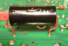
See picture attached. The one on the left used recycled "Iron" from an old EL84 amp. The one on the right has new Hammonds. The red arrows are pointing to the attachment screws that secure the PS choke to the underside of the chassis. The one on the left has the rectifier tube mounted off-board. The one on the right is the standard SPP with the GZ34 on the board. The board is secured to the chassis top plate with, IIRC, 19 or 20mm threaded spacers.
All of the components, except the tube sockets, can be mounted on either side of the board. On my two builds the tube sockets and couple of low wattage resistors were mounted on the top of the board. All other components were mounted on the bottom.
As you can see, the tubes are out front, OPRs behind and the speaker connectors behind the OPTs. Note how the orientation of the OPTs is rotated 90 degrees relative to the power trans. This is to prevent magnetic coupling leading to hum in the amp. Also the Choke is orientated 90 degrees to the power trans.
As mentioned previously, you might want to purchase a chassis with a slightly larger internal height. You will be less restricted on parts choices, especially the larger electrolytic caps.
Cheers, S
Attachments

Steve, I've been looking at a post you placed on a similar thread https://primarywindings.com/product/25w-7600-ohms-ultra-linear-push-pull-output-transformer/
It's a Standup 25W 7600 Ohms Ultra Linear Push Pull Output transformer, priced at Excl VAT £81.61
Sadly, Primary Winding U.K. don't appear to have a Mains Transformer that matches Tubelab's requirements, but i've emailed them.
i.e. 300-0-300 VAC minimum 175mA; Rectifier filament should be 5 VAC at least 3 amps (with a 5AR4 valve); Main filament should be 6.3 VAC at least 4 amps.
With begin a search for a case/chassis....
Some further questions please.
C101 (no value given) in the circuit diagram is the feedback compensation capacitor.
Tubelab tells us: -
'It is not installed at this time. The value is highly dependent on the type of output transformers that are used. The value can be determined by measurement or listening tests. It may not be needed at all in some builds'.
What sort of value/types/voltage might be suggested?
If possible can some detail be given about the Upgrades and this includes C103 & C105 = 0.1uF 450V / 630V ?
Also from where could i find the things that would be fitted into the holes drilled for the valves, so as to cover up the space between the valve and drilled holes?
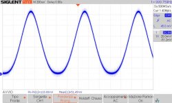
To determine the value of C101 you need a square wave generator with about 10kHz.
You have to look at the result with an oscilloscope.
The value will be between 100pF to 800pF.
You can also determine the value with your ears.
Look here:
https://www.diyaudio.com/community/...ensation-capacitor-on-the-tubelab-spp.201612/
https://www.diyaudio.com/community/threads/tubelab-simple-p-p.148694/post-6492730
- Home
- Amplifiers
- Tubes / Valves
- Tubelab SPP first timer build