Russ, I have a question on your rotary switch design - you have it set up so that there is a minimum resistance always present so you can switch it on the fly.
What is the harm of letting the switch go open in between "clicks" on the dial? The resistor essentially goes infinite and shuts off bias current... does this make a "pop" on the output or is it bad for the tubes? or is it more insidious - say the bias voltage could approach the screen voltage and the screen tries to draw current - and then something else I'm not seeing happens...
What is the harm of letting the switch go open in between "clicks" on the dial? The resistor essentially goes infinite and shuts off bias current... does this make a "pop" on the output or is it bad for the tubes? or is it more insidious - say the bias voltage could approach the screen voltage and the screen tries to draw current - and then something else I'm not seeing happens...
Hello,
Anyone built the SE with One Electron opt? What is the value of the supplemental capacitor (oil-filled)? Tanks. Godspeed.
John Revilla
Anyone built the SE with One Electron opt? What is the value of the supplemental capacitor (oil-filled)? Tanks. Godspeed.
John Revilla
oldmanStrat said:Russ, I have a question on your rotary switch design - you have it set up so that there is a minimum resistance always present so you can switch it on the fly.
What is the harm of letting the switch go open in between "clicks" on the dial? The resistor essentially goes infinite and shuts off bias current... does this make a "pop" on the output or is it bad for the tubes? or is it more insidious - say the bias voltage could approach the screen voltage and the screen tries to draw current - and then something else I'm not seeing happens...
My main concern was the bypass cap across the resistor. If the resistor went away, the only thing left to pass current to the cathode is the cap. It will charge-up quickly and probably will keep going past its rated voltage.
Multi-position switches have a designation on them regarding contact logic.
The most prevalent is the "Make before break" or...making both contacts (Parallel load) before the 'intended' goal load (Next contact).
The other designation is of course "Break before make" which is the designation that you are fearfull of because of its momentary "open" contact.
____________________________________________________Rick....
Attachments
I considered the option of a "make before break" or "shorting" switch, but I don't like to rely on switch contacts to be the only line of defense between joy and an exploding capacitor.
Anyone built the SE with One Electron opt? What is the value of the supplemental capacitor (oil-filled)? Tanks. Godspeed.
I have a pair of One Electron OBT-2's. I originally bought them for a Tubelab SE with 45's. They have been in several amps including the Simple SE. They are very good transformers with good sound quality. The 4.8K ohm version would be more suited for a Simple SE. I also have a pair of Edcor CXSE25-8-5K transformers. I would choose them over the One Electrons since they are about the same price. The Edcors are much larger than the One Electrons, which could be a problem in some designs.
The supplemental capacitor should be a motor run cap (NOT a start cap). These have characteristics that tend to offset the shortcomings of the electrolytic caps used in the board. The exact value is not critical. The capacitor must be rated for 370 VAC or 440 VAC and at least 40 uF. Use what ever that you can find cheap that fits this criteria. 50 to 100 uF 370 VAC caps can often be found on Ebay for $10 to $15.
What is the harm of letting the switch go open in between "clicks" on the dial? The resistor essentially goes infinite and shuts off bias current... does this make a "pop" on the output or is it bad for the tubes? or is it more insidious
In theory the cathode voltage would rise until the voltage gets high enough to cut off the output tube. A pop may be heard when the resistor is then switched back in. This is what USUALLY happens. It is possible for the voltage to rise above the voltage rating of the cathode cap causing it to leak some current. This current turns on the output tube, causing more current to flow through the cap. A runaway condition occurs leading to a big stinky mess of exploded capacitor. It CAN and does happen. I did it!
The simplest way to avoid this is to put a fairly large resistor in the board (820 or 1000 ohm) and switch resistors in parallel with it. If the switch fails, the tube defaults to its lowest current. Any switch can then be used.
The power transformer transformer I got from them are the first I've seen that doesn't display a flat-topped waveform when rectified and ran close to the VA rating. It still looks like a sine wave
Hi.
Just wondering what the sonic implications are for the distorted power transformer output? I am thinking of swapping out a Hammond transformer for an Edcor mainly to get the voltage up to where I wanted it int the first place.
(not for a tubelab, my own creation.)
Thanx.
A runaway condition occurs leading to a big stinky mess of exploded capacitor. It CAN and does happen. I did it!
Some how I don't doubt that. 😉
I hope you and Sherry are having a good week together.
how much current Max current for Edcore GXSE10-8-2.5K ?
I have not tried any of the GXSE transformers, so I don't know.
Thanks George for responding. Russ, you are the man! Can I use 6550 tubes too, I accidentally ordered a match quad. Thanks. Godspeed.
6550s are pretty similar to KT88s. At least some of the current-production tubes use the same innards for both.
Ryssen said:how much current Max current for Edcore GXSE10-8-2.5K ?
Edcor makes great transformers, but they're a little reluctant to share all the specifications. Ed is trying to build a compilation of data on their line. According to legend, the GXSE10 is rated for 60mA DC on the primary. Don't take this number as gospel.
http://www.diytube.com/phpBB2/viewtopic.php?t=3482
Hello,
Fired up my SE today for testing. First with rectifier not in place, all filaments lit. After 5 minutes with no smoke coming out, I placed the rectifier in its socket and turn it on again. Again, no problems whatsoever. Then.....
I proceed on measuring hum in both channels. Input were shorted and started measuring the right channel......1 to 2 mv. Great! left channel............57mv!! What is wrong?
I checked and re-checked grounding according to the manual. Input connector common (R-channel) connected to the MAIN grounding lug. Common on both OPT secondaries connected to the MAIN grounding lug. Cases of OPT, Choke, and Power Tranny ALL connected to the Main grounding lug and the Main grounding lug is connected to the IEC ground lug.
Please help me if this is not correct. I'm confused!
Thanks
John Revilla😕
60 hz humm?
are all of your input, OPT and AC wire pairs twisted?
Are you using an optional motor start cap? choke?
can you post a picture of your setup?
are all of your input, OPT and AC wire pairs twisted?
Are you using an optional motor start cap? choke?
can you post a picture of your setup?
Hi oldmanStrat,
Yes, I'm using a choke and a filter cap. All OPT wires and choke as well as power wires twisted. My input wires are not twisted but they are shielded. I'll post picture of the inside in a bit. Thanks.
John Revilla
Yes, I'm using a choke and a filter cap. All OPT wires and choke as well as power wires twisted. My input wires are not twisted but they are shielded. I'll post picture of the inside in a bit. Thanks.
John Revilla
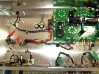
hmm looks like a nice tight build.
input jacks on the left? output on the right?
can't really tell what you have done with the inputs. Looks like a connector that I've not used before.. the pointy section goes to something on the top plate and the lug attach goes to a bundle that seems to exit the top too... oh, and a wire that is wrapped in a circle is also an inductor - but probably not your problem.
Where is your main ground?
I also see a bundle of wires - orange brown blue that may or may not be grounds or other things. What are these?
A single point of contact for grounds is the best way to avoid loops - if you didn't already know that.
Lots of wires are tied off with heat shrink. I'm especially interested in the ones on the OPTs, which I assume are bottom left. UL taps?
OldmanStrat,
Thanks for your comments. The OPT wires are the black(common) and green (8 ohms). The single yellow wire on the left is the circuit ground connected to the ground lug of the IEC. The orenge wire in the bottom is the input ground and the brown wires are the speaker post ground. The blue wires are for the OPT ground. No UL tap.
Anyway, No more hum!!!Yippeeeee!! I forgot to remove the contact from the lug to the bolt of the main power tranny. This caused the loop with the opt grounds and the single star point at the IEC. All music now. Hum measurement on both channels read.......tadaaaa......0mv! i'll roll EL34s, 6550s, kt88s and 6l6s tonight. Godspeed.
John Revilla
- Status
- Not open for further replies.
- Home
- More Vendors...
- Tubelab
- Tubelab Simple SE with big honkin' Edcors?