This brings up a question- the checkout procedure says to hook the speakers directly to the board and then connect a source and play music after the initial checkout.
It says "Connect a load to the amp, speakers or resistor." It says this after you have hooked up all three transformers, and a choke if used. You would connect your speakers or load resistor to the appropriate secondary of your OPT's.
If I can play music directly off the board, why do I need output transformers?
You can't play music on most tube amps without an output transformer. The tubes work at high voltages and low currents. The speakers work at much lower voltages and fairly high current. The output transformer uses a fixed ratio conversion raising the Current and lowering the Voltage while keeping the Power constant (Watts).
It would be like trying to make a car without a transmission. The engine runs at thousands of RPM with a few hundred Ft/Lbs of torque. The wheels need hundreds of RPM and thousands of Ft/Lbs of torque. The gears in the transmission and differential perform a similar conversion raising the Torque and reducing the RPM while keeping the power constant.
Note that it's not a coincidence that 1 Horsepower = 746 watts.
Thanks for the detailed explanation, Mr. Tubelab!
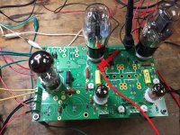
Tomorrow, this here TSE-II will be playing some sweet music.
After I get a potentiometer. Don't think the neighbors will appreciate even 1.5 - 2 watts through some Klipsch Cornwall speakers...
Tomorrow, this here TSE-II will be playing some sweet music.
After I get a potentiometer. Don't think the neighbors will appreciate even 1.5 - 2 watts through some Klipsch Cornwall speakers...
She's all checked out and ready for assembly into a chassis! Sounds really good on my bts, highly used and abused Boston Acoustics speakers and 18 gage wire interconnects. I also removed the potentiometer and connect directly to a 3.5mm jack on the iPod and RCA jacks connected to the amp inputs. B+/- voltages are stable, bias amps are stable. I'll start working on the chassis this weekend, hope to finish next week.
Thank you to Tubelab for all the time and effort to design, manufacture and post information about the Tubelab amps. This is what DIY is all about!
Thank you to Tubelab for all the time and effort to design, manufacture and post information about the Tubelab amps. This is what DIY is all about!
Attachments
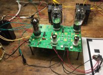
Thanks! Now I see why so many people like the 45 tubes. This amp sounds so nice...
It's kind of bad on my budget because now I'm going to build one of these boards for 300B tubes.
It's kind of bad on my budget because now I'm going to build one of these boards for 300B tubes.
Thanks! Now I see why so many people like the 45 tubes. This amp sounds so nice...
It's kind of bad on my budget because now I'm going to build one of these boards for 300B tubes.
lol.
Yeah, I really like my 45 TSE. I was going to make a 300b amp, but decided to go 45 instead, but mine is a headphone amp and I don't need the extra power.
Hi.
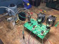
I was searching, but had no luck finding which fuse to use for this amp. on primary hot side of the power transformator with 230vac (and 115vac for US users also)...
Thing is also that my variac is kindoff smalish, only rated at 0.7A/240vac, but i guess for checkout and powering up first time it will do
My build is the 300b version, powertransformer will be toroidal 250VA
Jesper.
Fuse size
I'm running on 120 vac in the US. My amp had blown a 1 amp fuse initially. I now have a 2 amp and it is operating fine. It probably draws somewhere between 1 and 2 amps at 120 vac. So I suppose at 240 vac, the current would be halved.
I'm running on 120 vac in the US. My amp had blown a 1 amp fuse initially. I now have a 2 amp and it is operating fine. It probably draws somewhere between 1 and 2 amps at 120 vac. So I suppose at 240 vac, the current would be halved.
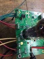
Inserted the 5842 tubes into their sockets and put a positive meter lead on the coupling cap nearest the 5842 tube, (C9 and C11), and the negative lead to ground. Adjusting R9 and R20 to around 175 Vdc.
Powered down and a few minutes later connected some bts crummy speakers to the OPT connectors: L-OPT-1 is red and L-OPT-2 is black. R-OPT-2 is black and R-OPT-1 is red. Installed the 45 tubes and leads across R18 and R29. Adjusted R12 and R23 to 27mA.
With all tubes installed, B+=339 Vdc, B-=-161.4 Vdc.
This brings up a question- the checkout procedure says to hook the speakers directly to the board and then connect a source and play music after the initial checkout.
If I can play music directly off the board, why do I need output transformers?
Measuring at the output tube pins, B+ = ~323.8 V dc, B- = -78.4.
The measurements listed with all tubes installed were measured at R30 for B+ and R6 for B- without output tubes installed.
Hi folks need some help, I don't find specific information on how to wire output tranformers.
Reading this useful thread but no luck.
Will read again TSE wiring instruction, any help appreciated.
Thanks
gmonno
Reading this useful thread but no luck.
Will read again TSE wiring instruction, any help appreciated.
Thanks
gmonno
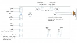
Everything looks right.
The Center Tap of the HV secondary goes to the connector in the lower left of your drawing. You have this labeled red-green. On most transformers that use the standard colors this is a red-yellow wire. Yours may be different.
The Center Tap of the HV secondary goes to the connector in the lower left of your drawing. You have this labeled red-green. On most transformers that use the standard colors this is a red-yellow wire. Yours may be different.
Tubelab : The Center Tap of the HV secondary goes to the connector in the lower left of your drawing. You have this labeled red-green
gmonno : my error -- THANKS - error and image corrected.
Duke58 and all : thanks for sharing your work.
gmonno : my error -- THANKS - error and image corrected.
Duke58 and all : thanks for sharing your work.
Attachments

Last edited:
Ready to go.....and just discovered that I mounted 300B sockets on reverse.
Filament pins are were should be anode-grid .. and reverse.
Now will have to undo some work before calling it done.
Filament pins are were should be anode-grid .. and reverse.
Now will have to undo some work before calling it done.
I see people have capacitors across the power switches in some photos. Anyone have insight into what values, and how to wire? I see a lot of conflicting info about wiring across the switch vs. parallel with the load (how would I do this) vs. adding a resister as well, etc. . . I have a .001uf little cermaic cap rated for 3000V -- would this work?
- Home
- More Vendors...
- Tubelab
- Tubelab SE-II Checkout