Don't mean to overpost, but I'm also wondering if it would be a bad idea to make a star ground point attached to a PT mounting bolt where it meets the chassis (i.e. the circled one in the picture below). It would be a convenient place to ground the power inlet, the PCB, and the input/output jacks, and also serves as a grounding connection for the PT housing. Too many grounds in one spot?
 gound-point by jeffdrouin, on Flickr
FYI, I sprayed a light coat of paint inside the chassis to prevent the aluminum from oxidizing, and then ground away the paint around the mounting holes for the PT, OPTs, and choke. The idea being to ground their metal housing through the bolt/washer's contact with the chassis.
gound-point by jeffdrouin, on FlickrFYI, I sprayed a light coat of paint inside the chassis to prevent the aluminum from oxidizing, and then ground away the paint around the mounting holes for the PT, OPTs, and choke. The idea being to ground their metal housing through the bolt/washer's contact with the chassis.
Last edited:
The input hot and return should run twisted together right to the board. Small coax is also good. The rca jacks will need to be isolated from the chassis. If your not using grommets where the wires come through the chassis at least put a few layers of heatshrink on them.
Don't mean to overpost, but I'm also wondering if it would be a bad idea to make a star ground point attached to a PT mounting bolt where it meets the chassis (i.e. the circled one in the picture below). It would be a convenient place to ground the power inlet, the PCB, and the input/output jacks, and also serves as a grounding connection for the PT housing. Too many grounds in one spot?
FYI, I sprayed a light coat of paint inside the chassis to prevent the aluminum from oxidizing, and then ground away the paint around the mounting holes for the PT, OPTs, and choke. The idea being to ground their metal housing through the bolt/washer's contact with the chassis.
Yes, a transformer bolt can be used as your star ground point.
I see you have set of eight of what I assume to be test jacks, 4 red and 4 black. Are the black jacks your ground jacks ?
If that is the case then you really only need one ground jack which can be used for testing with all the other red jacks.
OK, thanks. Evanc, in one of your pictures, it looks like there's a bare wire connecting to all the negative tabs on your input jacks (bottom right of the pic below), which then connects with a dark grey wire running to the star ground point. I'm just trying to figure out if I should do this too. My RCA jacks are insulated from the chassis.
Last edited:
That set up had a low level hum. I since have changed the input wiring to tiny coax with the hot and shield/ground going right to the board. Dead silent even driving very efficient compression drivers.
I can't get a photo right now. The amp is at "work". It has seen daily use for the last year flawlessly.
I believe the two pads left of where the hot inputs connects to the board in the above photo are ground connections....perfect for keeping the input hot and return close together.
I can't get a photo right now. The amp is at "work". It has seen daily use for the last year flawlessly.
I believe the two pads left of where the hot inputs connects to the board in the above photo are ground connections....perfect for keeping the input hot and return close together.
Last edited:
Ok thanks. I understand now. I'm going to try without, and will add a ground connection if there's hum.
Wiring the PT to the board now and could use a confirmation about one or two things. Here's the manufacturer's schematic:
 pt-schematic by jeffdrouin, on Flickr
I'm aiming for a B+ of about 400V in this 300B implementation, so I gather the 660V grouping is what I want to wire to T1-4 and T1-5, and not the 720V grouping. Correct?
I'm clear that the yellow wires for 5V grouping get soldered to T1-2 and T1-3, and that the green wires for the 6.3V grouping go to T1-7 and T1-8.
Would you please confirm that the following is correct?
* Green/yellow center tap wire to T1-6 (Zero in 6.3V grouping)
* Red/white wires to T1-4 and T1-5 (660V grouping)
* Red/yellow center tap to T1-1 (Zero in 660V grouping)
* The one black wire in the PT is on the primary side and gets wired to the ground lug of the power receptacle.
* Since I'm in the U.S., the brown (120V) wire goes to the hot lead on the power receptacle.
* All other wires are not used and shall be insulated (using shrink tubing) and kept out of the way.
Thanks in advance for taking a minute to check this!
pt-schematic by jeffdrouin, on FlickrI'm aiming for a B+ of about 400V in this 300B implementation, so I gather the 660V grouping is what I want to wire to T1-4 and T1-5, and not the 720V grouping. Correct?
I'm clear that the yellow wires for 5V grouping get soldered to T1-2 and T1-3, and that the green wires for the 6.3V grouping go to T1-7 and T1-8.
Would you please confirm that the following is correct?
* Green/yellow center tap wire to T1-6 (Zero in 6.3V grouping)
* Red/white wires to T1-4 and T1-5 (660V grouping)
* Red/yellow center tap to T1-1 (Zero in 660V grouping)
* The one black wire in the PT is on the primary side and gets wired to the ground lug of the power receptacle.
* Since I'm in the U.S., the brown (120V) wire goes to the hot lead on the power receptacle.
* All other wires are not used and shall be insulated (using shrink tubing) and kept out of the way.
Thanks in advance for taking a minute to check this!
Last edited:
Wiring the PT to the board now and could use a confirmation about one or two things. Here's the manufacturer's schematic:
I'm aiming for a B+ of about 400V in this 300B implementation, so I gather the 660V grouping is what I want to wire to T1-4 and T1-5, and not the 720V grouping. Correct?
Yes, 660V grouping.
Would you please confirm that the following is correct?
* Green/yellow center tap wire to T1-6 (Zero in 6.3V grouping)
Yes, 660V grouping.
No need to connect CT of 6.3v rail.
Rest please check with folks who have already done a build. Also please check the terminal numbers e.g. T1-6,T1-4 etc.
Last edited:
Thanks for the reply, zman01. The other builders I've checked with, including Roberto Akira (Tubelab SE | Roberto Akira) who was nice enough to give me his illustrated build notes, do include the CT for the 6.3V grouping. You can also see it in evanc's interior pics. Did you do something different with your TSE?
EDIT: Zman01, I just saw your link re: the 300B and 6.3V CT in another thread. Man, I keep forgetting how much info is bundled into those Tubes & Applications pages that George wrote. So, now that I know CT is not required (but optional?) I need to go learn why.
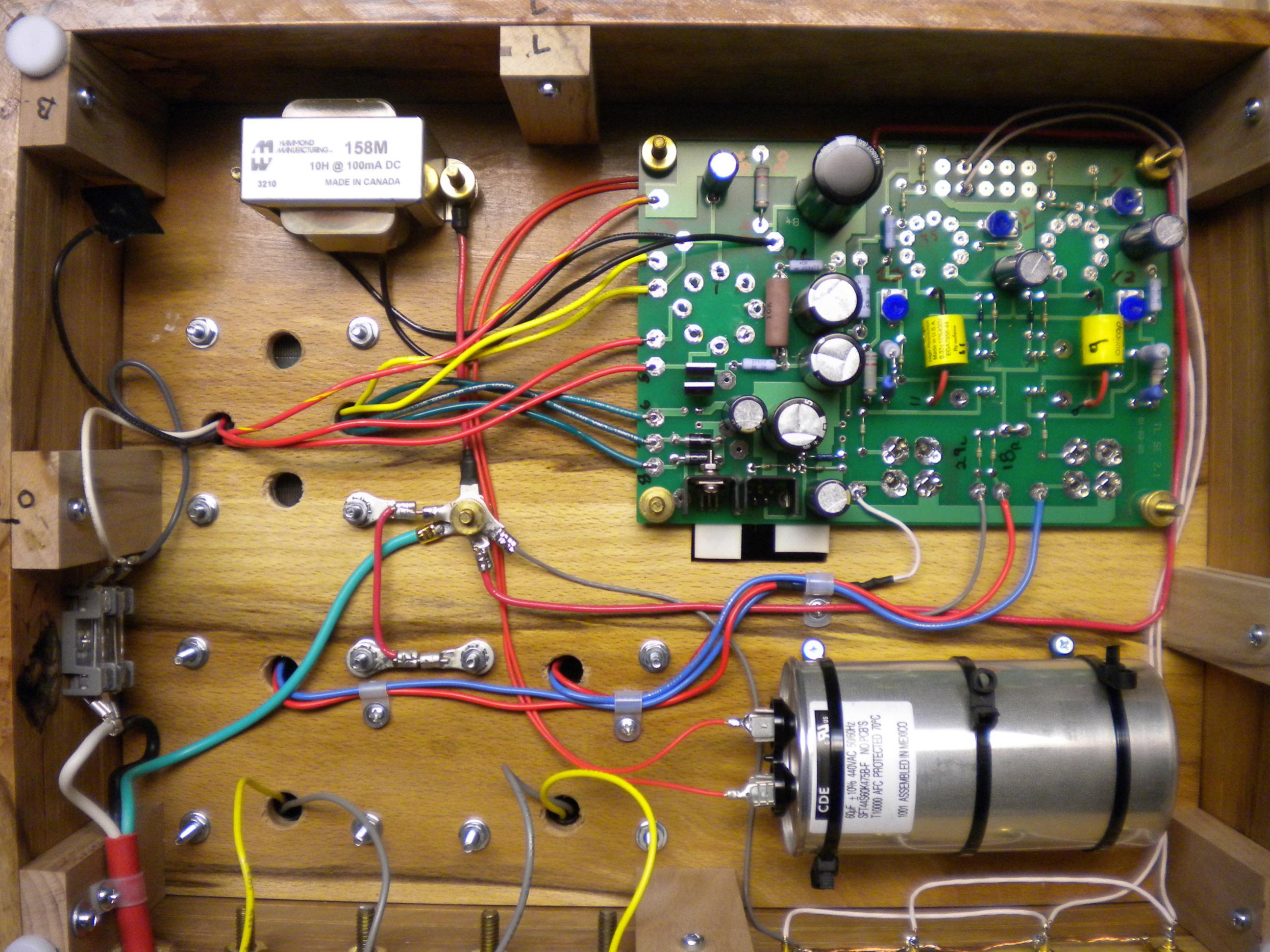
I've finished wiring the board and magnetics based on how I understand the TSE and PT schematics.
 Wired PCB by jeffdrouin, on Flickr
I still have to ground the speaker binding posts, PCB, wire the tip jacks, etc., but am now turning my attention on the power inlet.
I've got a combination IEC inlet, fuse, and switch, and am trying to figure out how to wire it.
 IEC inlet by jeffdrouin, on Flickr
I measured the AC voltage in the surge protector that the amp will be plugged into at 121.8 VAC.
The primary side of my PT (schematic in the posts above) has a Blue 125V wire, a Brown 120V wire, and a black 0 wire. From what I've read, the standard coloration is that brown is live, blue is neutral, and green/yellow is ground-earth. Does that mean that the black "0" wire on my PT primary is ground-earth?
If so, then I'd want to do the following:
* Blue and brown wires going from the PT to the wider switch tabs
* A brown wire going from the narrower switch tab to "L" on the receptacle side
* A blue wire going from the narrow switch tab to the "N" on the receptacle side
* A black wire would go from the ground tab on the receptacle side to the chassis ground point, where it would meet the black "0" wire coming from the primary side of the PT.
This picture seems to match pretty closely what I'd need to do, except for the ground.

This seems pretty straightforward but figured I'd better check in the interest of safety.
Thanks!
EDIT: Zman01, I just saw your link re: the 300B and 6.3V CT in another thread. Man, I keep forgetting how much info is bundled into those Tubes & Applications pages that George wrote. So, now that I know CT is not required (but optional?) I need to go learn why.
I've finished wiring the board and magnetics based on how I understand the TSE and PT schematics.
Wired PCB by jeffdrouin, on FlickrI still have to ground the speaker binding posts, PCB, wire the tip jacks, etc., but am now turning my attention on the power inlet.
I've got a combination IEC inlet, fuse, and switch, and am trying to figure out how to wire it.
IEC inlet by jeffdrouin, on FlickrI measured the AC voltage in the surge protector that the amp will be plugged into at 121.8 VAC.
The primary side of my PT (schematic in the posts above) has a Blue 125V wire, a Brown 120V wire, and a black 0 wire. From what I've read, the standard coloration is that brown is live, blue is neutral, and green/yellow is ground-earth. Does that mean that the black "0" wire on my PT primary is ground-earth?
If so, then I'd want to do the following:
* Blue and brown wires going from the PT to the wider switch tabs
* A brown wire going from the narrower switch tab to "L" on the receptacle side
* A blue wire going from the narrow switch tab to the "N" on the receptacle side
* A black wire would go from the ground tab on the receptacle side to the chassis ground point, where it would meet the black "0" wire coming from the primary side of the PT.
This picture seems to match pretty closely what I'd need to do, except for the ground.
This seems pretty straightforward but figured I'd better check in the interest of safety.
Thanks!
Last edited:
Stop!
Do not put 120v across the brown and blue transformer leads! You could fry your transformer if you do that.
Since your measured mains voltage is closer to 120v, you will use the brown and black leads.
The blue lead would be used if you had a higher mains voltage and wanted a lower secondary voltage. Cap off the blue lead and do not use it. If your secondary voltage is too high you can swap the brown lead with the blue lead to lower the output voltage.
Look at your transformer schematic again, it is quite clear if you understand how a transformer works.
The black lead is not ground, it is the other side of the primary winding.
Please research how a transformer works before you hook it up and hurt/kill someone.
Brown or blue from your transformer to the live and black from your transformer to neutral. ground from the power inlet right to the chassis with the shortest wire possible.
Well my soldering station just died so I've got a few days more to look into this. Will read up on PTs for sure.
I'll be playing the TSE directly from a CD player at first and have been thinking about volume pot wiring. I haven't been able to turn up much information about it by searching the forum, except for this thread initiated by gmonno.
There are two possibilities that I'd love to get some opinion on.
This one from gmonno, which uses all five pads in each channel:
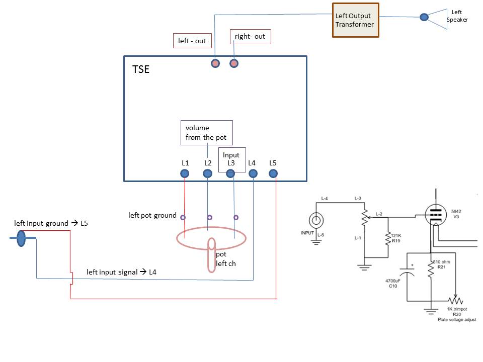
And the one attached below, also from gmonno in a private message, that uses only pads 1-3 in each channel. He used the attached one for a time but felt the amp was too quiet, so he started using a preamp and removed the volume pot from the TSE. He doesn't remember if he tried the first version above, as it was a while ago, and suggested I post them both here.
Thanks for any advice you guys might have on this.
Also, it turns out the husband of one of my colleagues is starting a hi-fi business (http://www.swansongaudio.com/) and offered to let me start the amp in the safe environment of his shop. It's definitely the wise thing to do, so hopefully we'll have good things to report later this week.
There are two possibilities that I'd love to get some opinion on.
This one from gmonno, which uses all five pads in each channel:
And the one attached below, also from gmonno in a private message, that uses only pads 1-3 in each channel. He used the attached one for a time but felt the amp was too quiet, so he started using a preamp and removed the volume pot from the TSE. He doesn't remember if he tried the first version above, as it was a while ago, and suggested I post them both here.
Thanks for any advice you guys might have on this.
Also, it turns out the husband of one of my colleagues is starting a hi-fi business (http://www.swansongaudio.com/) and offered to let me start the amp in the safe environment of his shop. It's definitely the wise thing to do, so hopefully we'll have good things to report later this week.
Attachments
Last edited:
I have a 6.3V pilot light that I want to use just to show that the amp is turned on. Can I run a pair of wires from the 6.3V pads on the PCB to the solder tabs on the light?
Since it's plastic construction and isolated from the chassis, do I still need to connect it to ground?
In most of the wiring jobs I've found online, people seem to use these things in guitar amplifiers by connecting the 6.3V wires from the PT to the pilot light, and then run wires from the light to the heaters. I don't want a blown bulb to turn off the amp -- this is just a simple on/off indicator visible from the front.
I have a 6.3V pilot light that I want to use just to show that the amp is turned on. Can I run a pair of wires from the 6.3V pads on the PCB to the solder tabs on the light?
Since it's plastic construction and isolated from the chassis, do I still need to connect it to ground?
In most of the wiring jobs I've found online, people seem to use these things in guitar amplifiers by connecting the 6.3V wires from the PT to the pilot light, and then run wires from the light to the heaters. I don't want a blown bulb to turn off the amp -- this is just a simple on/off indicator visible from the front.
You'll want to check if it is a 6.3V AC or DC pilot light first. If AC, just attach to T1-7 & T1-8. If it is DC, attach to F-4V and F-6V.
I managed to wire the power inlet last night, however I was very tired and was using a brand new soldering station that doesn't perform quite the same way as my old one. The combination of hampered judgment and an unfamiliar machine led to some pretty ugly work, though the connections are strong. A couple of the tabs shifted slightly as the plastic housing started to melt. It seems to be intact but I'll probably order a new inlet anyway.
 IEC wiring by jeffdrouin, on Flickr
The pilot light is one of the el cheapo Fender knockoffs at Angela that uses the #47 automotive lightbulb, so I think it's DC.
 IEC wiring by jeffdrouin, on Flickr
IEC wiring by jeffdrouin, on FlickrThe pilot light is one of the el cheapo Fender knockoffs at Angela that uses the #47 automotive lightbulb, so I think it's DC.
IEC wiring by jeffdrouin, on FlickrMaking progress!
I started the checkout procedure today, up to inserting the rectifier tube, putting in a 5842, and setting the plate voltage. The highest I was able to get was 163v with the potentiometer cranked all the way up. B+ was at 519v at that point, though I imagine that'll come down as more tubes are added in.
Right now the main concern is that R6 gets extremely hot. I'll see how it behaves as I proceed through checkout but I might need to replace it with a higher wattage resistor.
If R6 is getting extremely hot something is likely wrong. What MOFETs are you using, and where did you get them?
I installed a pair of Toshiba 2SK3565
2SK3565(Q,M) Toshiba Semiconductor and Storage | 2SK3565QM-ND | DigiKey
I am (was?) planning to use the Toshiba until I got everything else dialed in, then I'm going to try a pair of Fairchild FDP5N50NZF that evanc gave me, to see if there's an audible difference.
https://www.fairchildsemi.com/products/discretes/fets/mosfets/FDP5N50NZ.html
Last edited:
I just put in the second 5842. B+ was down to 454v and that tube also settled right in at 163v. Will set the output tube bias and listen tomorrow.
R6 does not seem to be getting as hot with more tubes in. I measured it at over 170*F with a probe this afternoon. After running for about a minute and half with two 5842s in place, it got up to 113*F. Different thermometer, though.
Also there is a slight mechanical hum in the PT. Is that normal?
R6 does not seem to be getting as hot with more tubes in. I measured it at over 170*F with a probe this afternoon. After running for about a minute and half with two 5842s in place, it got up to 113*F. Different thermometer, though.
Also there is a slight mechanical hum in the PT. Is that normal?
- Home
- More Vendors...
- Tubelab
- Tubelab SE 300b Build Thread