Thanks again zman01 and w5jag.
I finished soldering the semiconductors and capacitors. The only issue is that the cap I got for C6 is a snap-on type with a wide diameter that crowds out C7. I could add C7 if I leave the leads a bit long and tilt it off to a side.
Otherwise I could just replace C6. I visited an electronics store in town that seems to stock a lot of Sprague stuff. Not sure how it compares to Panasonic and Nichicon, which is what's currently on my board.
Could also be a good place to find a motor run cap or alternates for C4 & C5.
Jeff,
I am assuming that the C7 cap is a leaded one and not a snap in? I have limited knowledge in this area 🙂, but slightly longer leads and a bit of tilt should be ok. Do take care that C7 does not get pressed from the angle resulting in the leads getting tugged at - then the cap will get damaged and likely to fail.
Maybe you can take a pic with the leads inserted and the experts can chime in?
Last edited:
Here is a pic of C7 as I intend to solder it. It touches neither C6, which is on the right, nor the board. FYI I gently bent the leads of C6 so they would align with the holes in the board. The caps will hang from the underside of the board, while the resistors, sockets, and semiconductors are on top.
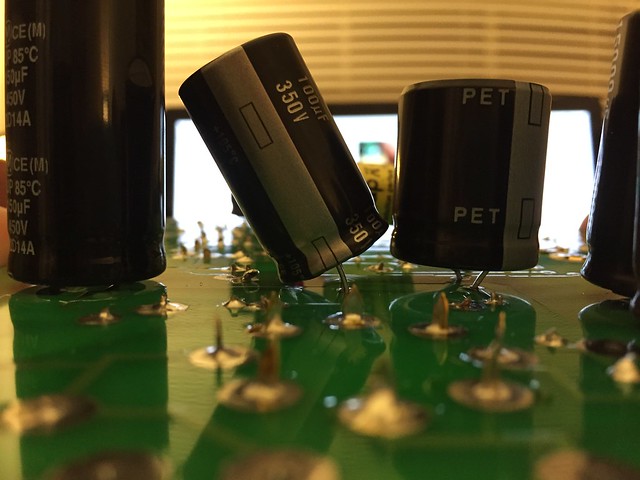 c7-tilted by jeffdrouin, on Flickr
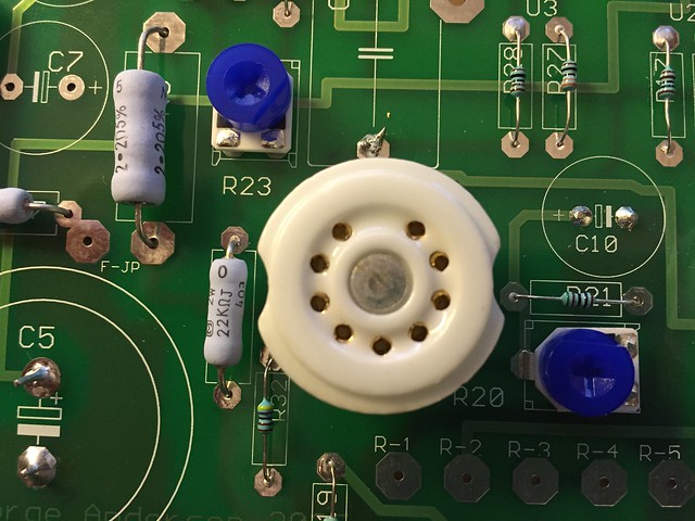
Tonight I soldered in the 4-pin sockets for the 300Bs and then tried to install tubes in all of them to make sure they fit. The GZ34 and 300Bs went into their tubes just fine, but I couldn't get the 5842s into the noval sockets.
It could be bad alignment between the female pin receivers and the ceramic cover of the socket:
 5842-top by jeffdrouin, on Flickr
Or perhaps some bent pins on the 5842s:
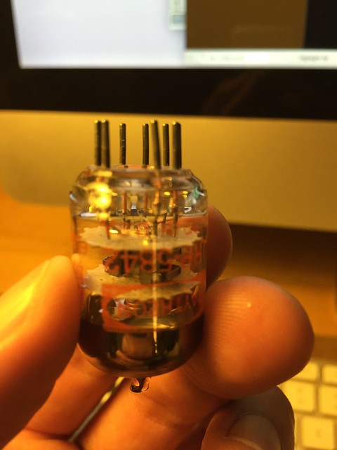 5842-pins by jeffdrouin, on Flickr
Any suggestions on how to remedy this? I figure my options are:
1. Try to reheat the solder and minipulate the pin receptacles into alignment from the lead tips sticking out on the bottom of the board or at the legs between board and socket (i.e. by nudging with needlenose pliers, a screwdriver, or somesuch).
2. Leave the solder alone but try to bring the pin receptacles into better alignment by gently nudging the legs with a screwdriver or somesuch.
3. Try to bend the tube pins--without placing stress on where they meet the glass housing--so that they are straighter and more in line with the socket receptacles.
Kind of wish I had soldered the 5842 sockets onto the board with the tubes in them. I really didn't think they'd deviate that far.
Thanks for everyone's suggestions so far. I really appreciate them.
c7-tilted by jeffdrouin, on FlickrTonight I soldered in the 4-pin sockets for the 300Bs and then tried to install tubes in all of them to make sure they fit. The GZ34 and 300Bs went into their tubes just fine, but I couldn't get the 5842s into the noval sockets.
It could be bad alignment between the female pin receivers and the ceramic cover of the socket:
5842-top by jeffdrouin, on FlickrOr perhaps some bent pins on the 5842s:
5842-pins by jeffdrouin, on FlickrAny suggestions on how to remedy this? I figure my options are:
1. Try to reheat the solder and minipulate the pin receptacles into alignment from the lead tips sticking out on the bottom of the board or at the legs between board and socket (i.e. by nudging with needlenose pliers, a screwdriver, or somesuch).
2. Leave the solder alone but try to bring the pin receptacles into better alignment by gently nudging the legs with a screwdriver or somesuch.
3. Try to bend the tube pins--without placing stress on where they meet the glass housing--so that they are straighter and more in line with the socket receptacles.
Kind of wish I had soldered the 5842 sockets onto the board with the tubes in them. I really didn't think they'd deviate that far.
Thanks for everyone's suggestions so far. I really appreciate them.
Last edited:
If you solder tube sockets unto a board with the tube in the socket, you stand an excellent chance of soldering the tube into the socket.
To straighten pins, it is best to use a pin straightener made for the task. My tester has them, I'm told they are also available on eBay.
You can do it with needle nose pliers - if you are very careful. I've done it dozens of times. But it's not a good practice.
Some of your solder joints look cold. In particular that one due north of the 9 pin tube socket in the above pic. Try to find some online pics of good solder joints and make sure all of yours look like that. Bad solder joints, from cold soldering or insufficient solder, will cause you problems on down the road. Often intermittent problems - the worst kind.
Win W5JAG
Last edited:
OK, thanks. Wow, I had no conception that something like a tube pin straightener would even exist. Learn something new every day.
That solder joint just north of the noval socket is actually stranded wire from the Auricap coupling capacitor, which is located under the board. I tried to cover the wire I couldn't clip off with some solder to keep the copper strands from oxidizing. I will look over that one, as well as the rest, to try and improve.
What would you say is a good solder joint? Something like the "north" one at R28, perhaps?
Solder did not flow through all of the holes to the top of the board, and I didn't worry about it because I preferred a minimalist approach.
Next question: Should I wait until my 50K attenuator volume control arrives (in about two weeks) to begin the checkout process, or can I start without it?
I can use the preamp out and volume control on my SS amp in the meantime, if necessary.
Last edited:
I put tubes in the sockets when I solder the sockets......
I've never had any issues with soldering a tube into the socket.
The way I figure it, if you soldered the tube into the socket then you would have filled the pin with solder anyway.......
Don't use too much solder.
Maybe i'm wrong
I've never had any issues with soldering a tube into the socket.
The way I figure it, if you soldered the tube into the socket then you would have filled the pin with solder anyway.......
Don't use too much solder.
Maybe i'm wrong
Straighten the pin a bit and wiggle the tube into place. I have often thought I put too much force into installing a tube but have never broken one on install. Maybe not a good idea for super expensive rare tubes but in this case.....
I like to see a bit of a solder on the top of the joint....just like I like to see a bit of squeeze out on a glue joint.
I like to see a bit of a solder on the top of the joint....just like I like to see a bit of squeeze out on a glue joint.
I put tubes in the sockets when I solder the sockets......
Is there a reason why you do this ?
Apart from the likelihood of soldering the tube pins to the socket it seems to me that in the case of a PCB
there would be some difficulty with a tube in the socket while soldering the socket to the PCB.
The north one at R28 looks fine.
On a pcb, the solder joint is both the electrical connection and holds the part in place. Personally, I don't use a minimalist approach with it. If the hole on the board is plated through, I use enough solder to flow through to the other side. I think the tubelab boards are only one layer, so it probably doesn't make any difference. It's just what I do.
If your board is finished, go ahead and check it out. Why wait? If something is amiss, you can fix it while waiting on the volume control.
Win W5JAG
Thanks for the eyes, everyone. I strengthened the cold joints. The board is done, though I still need to work these 5842s into the sockets.
I'm planning to start the checkout procedure this weekend.
I'm planning to start the checkout procedure this weekend.
OK, now I'm learning myself on heat sinking by reading through the forum threads. Seems a lot of TSE 300b builders have problems with the regulator shutting down due to overheating.
My enclosure is aluminum, fairly large at 17 x 10 x 3, and will have plenty of holes drilled into the bottom and top (directly over the PCB) for ventilation. Do you think I'll be OK with the originally spec'd heat sinks?
If not, I think I can add a larger heat sink to U1/D1 with thermal paste and a bit of aluminum flat stock as a shim. That would allow the larger sink to hang over the side of the board and protrude down, which is desirable since there'll only be about an inch of space between the board and the chassis top plate.
Do you think I'll need more heat sinking for Q1/Q2 and U2/U3?
Thanks,
Jeff
I added more heatsink to all the semis...they still get quite hot. I'll look for pictures when I get home.
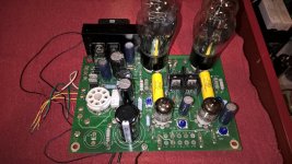
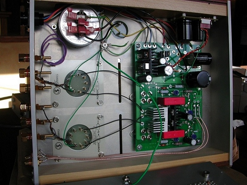
I dug out my old TSE board last night and took a photograph of it.
You can see my heatsinks, including the regulator chip heatsink. My regulator chip never shut down, but even with the heat sink pictured, it got hotter than I was willing to tolerate, so I installed the small fan seen attached to the sink.
It ran cool to the touch after that.
You can also see how I dealt with the c6 c7 spacing issue - I used a cap with leads at opposite ends of the cap, and then just bent the negative lead over the top and soldered it to the board. edit: maybe the positive lead - whichever went to ground potential.
Win W5JAG
Attachments
Last edited:
Thanks for taking the time to dig that out, Win. The picture is very helpful. Evanc: I'd love to see yours too.
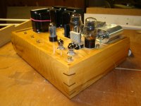
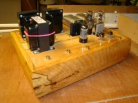
In the picture thread, Boywonder did a 300B build at 360V B+ and output tubes biased to 70ma. He seems to have used only some tidy heatsinks that conform to the size and shape of the original ones:
I'm going for 390-400V and 80-90mA (my OPTs are 5K:8ohm, 100mA, 15W), but will tweak and settle at whatever seems to sound best.
Hoping I can do this without using fans, but I have some I can pull from a Linux box I made 11 years ago if heat sinks and venting are not enough.
Last edited:

Thanks Evan. I'm curious about the wiring on the Auricap coupling capacitors. In George's pictures (and on my amp), the red wires face the 5842s, not the 300Bs. Have you done something different there?
I guess the idea is that one color is connected to the outside foil of the cap and works to shield the cap if installed a certain way. I don't believe this is a big deal in a power amp. Mine wired with coax for the input wire is humm free even driving very efficient compression drivers.
E
E
http://www.partsconnexion.com/prod_pdf/auricapxo-lead.pdf
"The outer foil lead is indicated by a black lead or a lead that is shorter than the other lead.
In all coupling applications the input going to the Auricap should be to the outer
foil and connected to the signal source or circuit output with the red or longer
lead continuing on to the next circuit input."
I might have them the suggested way.
- Home
- More Vendors...
- Tubelab
- Tubelab SE 300b Build Thread