That's good to know. I'll look into changing R6.
You blew a current regulator. U2, or U3 depending on channel. I did the same thing. It also blew the mosfet. I think the tube was still good even after glowing.
This is all great information. So hopefully after I lower B-, I should be finally done. Thanks a million.
You blew a current regulator. U2, or U3 depending on channel. I did the same thing. It also blew the mosfet. I think the tube was still good even after glowing.
This is all great information. So hopefully after I lower B-, I should be finally done. Thanks a million.
I haven't read though in detail. The -150 on the schematic is as the amp was originally designed for 45s. I had two builds for 300Bs with 400V B+ and B- was around -300V - no problems, and normal. In a third for EML 320Bs I ran 525V B+, though I used 10M90s and 900V MOSFETS in that one.
For the CCSs I've seen some large variances so I always measure the device and tune the current set resistor.
For the CCSs I've seen some large variances so I always measure the device and tune the current set resistor.
Has anyone actually talked to George and gotten an answer on this topic?
I would really like to know if I am done or note.
When by AC is at about 123 volts, my B+ is at about 375 volts, and my B- is at about -290 volts. These are approximate numbers as my AC drifts around a little.
I would really like to know if I am done or note.
When by AC is at about 123 volts, my B+ is at about 375 volts, and my B- is at about -290 volts. These are approximate numbers as my AC drifts around a little.
You blew a current regulator.
No, it blew the mosfet that does the impedance matching for the output tube (either Q1 or Q2 but I went ahead and replaced both). Mine is the FDP5N50NZ-ND that came from Digikey. The CCS's were fine. Music was playing fine and then I heard a low pop... music was gone... then back playing... then gone... then playing... then gone for good. That's before I lowered the voltage and that's the first time I noticed the 5842 plate glowing. Weirdest thing I've ever seen.
Last edited:
Has anyone actually talked to George and gotten an answer on this topic?
I would really like to know if I am done or note.
When by AC is at about 123 volts, my B+ is at about 375 volts, and my B- is at about -290 volts. These are approximate numbers as my AC drifts around a little.
The -150 being for 45s is from George. He's answered the question several times - buried in many threads here.
"Show me on the doll where the aliens touched you." - SY
Love the signature. Every time I read it, I die.
Guarnera:

SE Amp CAD says that in order to bias the 300B to 75mA @ 384V, you need -76V of B-. So -150V seems like plenty for the MOSFET to draw from. Raising the B+ requires slightly more B-. Lowering the plate idle current also requires more B-.
The only problem with raising R6 to 40K is that the second cap in the filter takes longer to charge but I don't know if there are any transients that the cap is required to fill since this is Class A. Maybe someone can answer?
The -150 being for 45s is from George. He's answered the question several times - buried in many threads here.
Well, I can't read through every post, But I do believe this. I read through the
webpage again. And George says that you can us 45's, 2A3's, or 300B's with out changing any parts.
So I guess I'm done. I have been running her 10 hours a day, trying to get 300 hrs. on my Psvane treasure II 300B's, with no problems. I have a 2.25" square fan inside the power supply unit aiming at the 5 volt regulator heat sink. I have run her for two hours without the fan on without the regulator shutting down. But when I run her for 10 hours straight I turn the fan on. You cant hear it when music is playing. But when its finally set up in the den, I probably won't use the fan much.
So now I'm waiting on my Quantum, CD transport to be completed. It should be done really soon. I'm supposed to be getting S/N 004. One, two, and 3 were prototypes, so I should be getting the first completed unit. Can't wait.
I want to thank everyone here for all the help on this project.

And George says that you can us 45's, 2A3's, or 300B's with out changing any parts.
If you're running 300V-350V R14 and R25 should be 30K. For 350V-400V they should be 36K. This is noted in the BOM.
If you're running 300V-350V R14 and R25 should be 30K. For 350V-400V they should be 36K. This is noted in the BOM.
Yes, I got that. they are 36K.
Well, I can't read through every post, But I do believe this. I read through the
webpage again. And George says that you can us 45's, 2A3's, or 300B's with out changing any parts.
So I guess I'm done. I have been running her 10 hours a day, trying to get 300 hrs. on my Psvane treasure II 300B's, with no problems. I have a 2.25" square fan inside the power supply unit aiming at the 5 volt regulator heat sink. I have run her for two hours without the fan on without the regulator shutting down. But when I run her for 10 hours straight I turn the fan on. You cant hear it when music is playing. But when its finally set up in the den, I probably won't use the fan much.
So now I'm waiting on my Quantum, CD transport to be completed. It should be done really soon. I'm supposed to be getting S/N 004. One, two, and 3 were prototypes, so I should be getting the first completed unit. Can't wait.
I want to thank everyone here for all the help on this project.
I am totally wrong about the Quantum CD transport. I don't know where I got that about 001 to 003 being prototypes. I must of imagined that. 003 went to the Netherlanders I believe? And got great reviews.Mine should be 004. Sorry for the confusion.

Hi Jdrouin,
I'm in the research of the perfect case and have to tell you that yours is the greatest and most elegant I have seen. This is why I'd like to ask you some questions about the building so that I can do something similar, if you don't mind.
Firs question would be, how did you do the case??? Did you buy just an aluminium sheet and then drilled and "folded"?? Drilling is no problem since I have appropriate hardware, actually giving the "case-form" is my concern..
Black drilled top case is also aluminium? Same process just painted in black?
Regarding to the painting did you use any specific heat resistant spray paint or just a normal one, those used for graffiti?
Thanks a lot for your time!
Hi capitanalga,
I used a Bud Industries aluminum chassis, size 17" x 10" x 3" and matching bottom plate from Amazon.
There are other manufacturers like Hammond that make similar products.
Rubber feet from Angela.
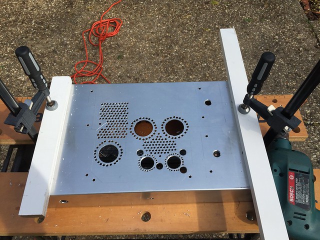
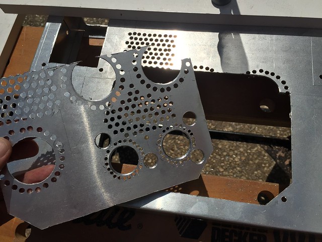
I printed out the drill guides from the Tubelab website to get the holes aligned, and then made up my own drill pattern for the venting.
The removable top panel and openings for the power transformer and IEC inlet I drew with a T-square and ruler, and then cut by hand with a rotary tool and Dremel #426 cutoff disc.
The paint is Rustoleum matte French cream for all surfaces, including aluminum. No high temp paint needed. This paint sticks well to the aluminum, though next time I might try spraying it with aluminum primer first.
Also, the case is large and thin enough to be a little wobbly, so I reinforced it with some aluminum flat bar and a couple of angle brackets. It was an easy improvement with cheap hardware parts.
Here's an inside pic of how it looks.
 Wired PCB by jeffdrouin, on Flickr
The angle brackets are bolted with the output transformer mounting bolts. The assembly puts enough tension across the top of the chassis that you don't have to drill into the sides to add more. It would be even more stable if I did that, but I made a compromise for the appearance because I wanted smooth side surfaces without a lot of bolts.
Also, I would leave the interior unpainted as it will lead to better chassis grounding. I'm currently making a phono preamp and will be using the same paint, but with unpainted insides.
Good luck!
Jeff
I used a Bud Industries aluminum chassis, size 17" x 10" x 3" and matching bottom plate from Amazon.
There are other manufacturers like Hammond that make similar products.
Rubber feet from Angela.
I printed out the drill guides from the Tubelab website to get the holes aligned, and then made up my own drill pattern for the venting.
The removable top panel and openings for the power transformer and IEC inlet I drew with a T-square and ruler, and then cut by hand with a rotary tool and Dremel #426 cutoff disc.
The paint is Rustoleum matte French cream for all surfaces, including aluminum. No high temp paint needed. This paint sticks well to the aluminum, though next time I might try spraying it with aluminum primer first.
Also, the case is large and thin enough to be a little wobbly, so I reinforced it with some aluminum flat bar and a couple of angle brackets. It was an easy improvement with cheap hardware parts.
Here's an inside pic of how it looks.
Wired PCB by jeffdrouin, on FlickrThe angle brackets are bolted with the output transformer mounting bolts. The assembly puts enough tension across the top of the chassis that you don't have to drill into the sides to add more. It would be even more stable if I did that, but I made a compromise for the appearance because I wanted smooth side surfaces without a lot of bolts.
Also, I would leave the interior unpainted as it will lead to better chassis grounding. I'm currently making a phono preamp and will be using the same paint, but with unpainted insides.
Good luck!
Jeff
Last edited:
Thanks a lot!! Box is on the way!!
I'll share seme pics once finished!
Thanks again
I'll share seme pics once finished!
Thanks again
Hi capitanalga,
I used a Bud Industries aluminum chassis, size 17" x 10" x 3" and matching bottom plate from Amazon.
There are other manufacturers like Hammond that make similar products.
Rubber feet from Angela.
I printed out the drill guides from the Tubelab website to get the holes aligned, and then made up my own drill pattern for the venting.
The removable top panel and openings for the power transformer and IEC inlet I drew with a T-square and ruler, and then cut by hand with a rotary tool and Dremel #426 cutoff disc.
The paint is Rustoleum matte French cream for all surfaces, including aluminum. No high temp paint needed. This paint sticks well to the aluminum, though next time I might try spraying it with aluminum primer first.
Also, the case is large and thin enough to be a little wobbly, so I reinforced it with some aluminum flat bar and a couple of angle brackets. It was an easy improvement with cheap hardware parts.
The angle brackets are bolted with the output transformer mounting bolts. The assembly puts enough tension across the top of the chassis that you don't have to drill into the sides to add more. It would be even more stable if I did that, but I made a compromise for the appearance because I wanted smooth side surfaces without a lot of bolts.
Also, I would leave the interior unpainted as it will lead to better chassis grounding. I'm currently making a phono preamp and will be using the same paint, but with unpainted insides.
Good luck!
Jeff
This is a choke that should work, but "ugly" as it's open frame:
http://www.mouser.com/ProductDetail/Triad-Magnetics/C-14X/?qs=R2jSSvul3fBpgK5gQ37xBA==
One PT which I found very close to George's recommendation, but again open frame and higher priced compared to other options:
http://www.mouser.com/ProductDetail...hhUu568dE5uZXflRiJDvMSKW5LYjJeX/fFSXf%2bVxw==
Folks have used this one too:
https://www.tedweber.com/wpt30
Going to go with Edcor's first to see if I can't put together a working unit.
Is this choke ok? EDCOR - CXC100-5H-200mA
And looking at these. DI need 2? EDCOR - XSE15-5K
Is this choke ok? EDCOR - CXC100-5H-200mA
And looking at these. DI need 2? EDCOR - XSE15-5K
- Status
- This old topic is closed. If you want to reopen this topic, contact a moderator using the "Report Post" button.
- Home
- More Vendors...
- Tubelab
- Tubelab SE 300b Build Thread