Hello folks,
I was looking for a diy tube preamp project, and found out this one which i think could be even better, but im newbie on this and need some opinions about.
I found a tube tone control baxandall. I want something that gives me some tube coloration and de bax filters is a plus coz i can shape sounds even further.
This pcb is being selled on eBay and Amazon. The sellers says its a good quality circuit, made to be built with good components.
I want to hear from u guys, what u think about this project. Can It give me some coloration + bax filters with a good audio quality?
Thanks,
An externally hosted image should be here but it was not working when we last tested it.
Here is the product info:
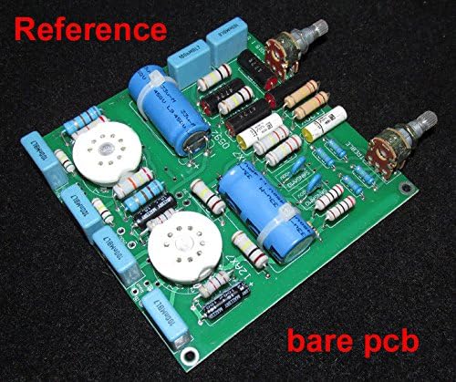
"This is a bare PCB of a low noise , tube based tone control stereo amplifier by means of two low noise triode tubes 12AX7.
The board is designed with high quality components in mind, including Wima film capacitors, silver mica capacitors,Philips electrolytic filtering capacitors, low noise metal film resistors and Mallory decoupling capacitors. Being a bare PCB, users can put in their components of their preference.
The board only requires a +250Vdc input voltage and 6.3V filament voltage.
Board thickness : 1.6mm, gold plated surface
PCB Dimension : 95mm x 108mm
Finishing : double-sided solder resist for best durability and reliability."
If you have to ask, you could do a LOT worse. This even has the 100k:130k correction for the non-infinite gain of a 12AX7.
Just do it. Let us know how it sounds.
Just do it. Let us know how it sounds.
This even has the 100k:130k correction for the non-infinite gain of a 12AX7.
And is this good or bad? Hehehe
Can u explain me this? Newbie on this, i didnt understand well what each components makes in the circuit.
Well yes its a quite cheap project, i have nothing to loose. I gonna try and let you guys know.
I need help on two things...
1- Power supply.
For this project i gonna need two Power DC Transformers to delivery +250Vdc and 6.3v, is that right?
Can u guys suggest me something good but not só expensive?
2- I want to make the inputs and outputs balanced. I need suggestions on How to do this. Transformers i supose. Any good but not so expensive option? Hehe
Thanks!
Well yes its a quite cheap project, i have nothing to loose. I gonna try and let you guys know.
I need help on two things...
1- Power supply.
For this project i gonna need two Power DC Transformers to delivery +250Vdc and 6.3v, is that right?
Can u guys suggest me something good but not só expensive?
2- I want to make the inputs and outputs balanced. I need suggestions on How to do this. Transformers i supose. Any good but not so expensive option? Hehe
Thanks!
Costs go way up, if balanced I/Ps and O/Ps are wanted. Magnetics never come cheap!
6.3 VAC heating should be OK, especially if you use Sovtek 12AX7LPS tubes. The New Sensor offering contains a hum bucking, spiral wound, heater.
The 12AX7 is a wimp and is not good at driving loads.
If you "full wave" voltage double the O/P of a Triad N-68X, you obtain "feedstock" for a voltage regulator. 100 or so mA. of B+ is plenty, for small signal circuitry.
Attachments

6.3 VAC heating should be OK, especially if you use Sovtek 12AX7LPS tubes. The New Sensor offering contains a hum bucking, spiral wound, heater.
The 12AX7 is a wimp and is not good at driving loads.
What you mean here is that 12AX7LPS would be better over regular 12AX7?
If you "full wave" voltage double the O/P of a Triad N-68X, you obtain "feedstock" for a voltage regulator. 100 or so mA. of B+ is plenty, for small signal circuitry.
Please could you explain me better, in some noobie language? Hehehe Sorry for this, im studing, but still a long way to understand those circuits well.
Thanks!
That tone stack needs a buffer at the output. A third tube setup as a cathode follower would make it significantly more useful.
Please someone can help me to understand this circuit better? Each tube is used on the baxandall shelfs? One for lows and other for highs? What exactly tubes does in this circuit? Does It manage the lows and highs boosts and cuts? Does this circuit seems to be well designed? Any down side?
That tone stack needs a buffer at the output. A third tube setup as a cathode follower would make it significantly more useful.
Thanks, sounds interesting. Could you explain me better your Idea and How can i make it?
Please someone can help me to understand this circuit better? Each tube is used on the baxandall shelfs? One for lows and other for highs? What exactly tubes does in this circuit? Does It manage the lows and highs boosts and cuts? Does this circuit seems to be well designed? Any down side?
V1 is a cathode follower. It is a buffer that provides a high input impedance, and a low output impedance to drive the tone circuit.
The Tone circuit is a standard Baxandall feedback circuit, boost and cut. Practical Tone Controls.
Yes the circuit is well designed, it makes good use of the tube. The output impedance is a little high but you can live with that for now. Go ahead and build it.
Baxandall finished his preamplifier with a 6BX6 wired as a cathode follower. From memory he drove the tone control stage with a stage of impedance about 1000 ohm. The stage feeding the tone control doesn't have to be a cathode follower but should have a low output impedance (say 1000 ohm or so). As such it may have useful gain.
Baxandall's original article is availale - The Wireless World Archive
The link is to the Wireless World archive; Baxandall was a contributor.
Baxandall's original article is availale - The Wireless World Archive
The link is to the Wireless World archive; Baxandall was a contributor.
Info about the self biasing cathode follower can be found here:
The Valve Wizard -Cathode Follower
Thank you! Gonna check!
Hi
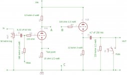
in attach a diagram of a line preamp with 6N6 double triode.
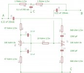
In Fig.2 the complete circuit with three point where you can connect the tone control in Fig. 3
It works great and the gain with 6N6 is 15 dB (5,5 times), with ECC88 we get 21 dB without any changes on circuit.
Connecting A with B you have a simply line preamp.
Inserting the circuit of Fig. 3 you can have the tone control.
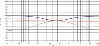
You can see also the response of the tone control with two tubes.
This circuit was presented by me on Audioreview in Italy.
I am preparing the boards also.
Walter
Walter
in attach a diagram of a line preamp with 6N6 double triode.
In Fig.2 the complete circuit with three point where you can connect the tone control in Fig. 3
It works great and the gain with 6N6 is 15 dB (5,5 times), with ECC88 we get 21 dB without any changes on circuit.
Connecting A with B you have a simply line preamp.
Inserting the circuit of Fig. 3 you can have the tone control.
You can see also the response of the tone control with two tubes.
This circuit was presented by me on Audioreview in Italy.
I am preparing the boards also.
Walter
Walter
Attachments


Walter's circuit is infinitely better thought out than the eBay PC board, I would strongly suggest building that instead.
I used 6922 to drive the (Passive) tone stack of an SX-780 feeding into the amplifier. outstanding results
The 6922 replaced the TA7136p op amp
Schematic similar to post #15 "A" from tube "B" to amplifier
The 6922 replaced the TA7136p op amp
Schematic similar to post #15 "A" from tube "B" to amplifier
Last edited:
Hey ctech,
Don't worry, when you say noob I know exactly what you mean. I personally understand about 20% of what people have offered in this thread. Maybe.
That's just the way the forum goes. These people are mostly really well meaning and very smart/knowledgeable about circuits, but they often have trouble dumbing things down for beginners.
I have one of those boards on the way from China right now and I am going to build it with quality (but not "audiophile") components. For the 250vdc supply, I am going to buy a transformer and then run it through a bridge rectifier and add some filtering. Not sure, but I will probably go with a simple C-R-C filter. For the 6.3vac I have a transformer and will just run that directly to the board.
It will be a long time before I build it, but that's my plan. I will be interested to see how your build goes.
I don't know/understand nearly as much as the other people in the thread, but I will try to explain things in a way that you can understand, if I can understand it myself.
Last edited:
What you mean here is that 12AX7LPS would be better over regular 12AX7?
Please could you explain me better, in some noobie language? Hehehe Sorry for this, im studing, but still a long way to understand those circuits well.
Thanks!
The triodes in a 12AX7LPS should be electrically equivalent to the triodes found in any other 12AX7 variant. The heater wire in a 'LPS is spiral wound, as opposed to being folded. Spiral winding bucks hum, when AC heating is employed.
The "full wave" voltage doubler is, in fact, 2X half wave rectifiers wired back to back. Some characteristics of true full wave rectification are present: the entire sine wave is used, no "standing" DC is applied to the power transformer's rectifier winding, and the ripple frequency is 2X the power line frequency.
Hi
in attach a diagram of a line preamp with 6N6 double triode.
In Fig.2 the complete circuit with three point where you can connect the tone control in Fig. 3
It works great and the gain with 6N6 is 15 dB (5,5 times), with ECC88 we get 21 dB without any changes on circuit.
Connecting A with B you have a simply line preamp.
Inserting the circuit of Fig. 3 you can have the tone control.
You can see also the response of the tone control with two tubes.
This circuit was presented by me on Audioreview in Italy.
I am preparing the boards also.
Walter, thank you so much! This project looks really interesting!
Will you sell the PCBs? Or can share the layout?
Do you think would be a good ideia to build It point-to-point without pcb? Seems to be not so difficult.
As long as I understand the circuit It is a mono tube preamp, and the figure 3 is a passive low and high shelf baxandall, is that right? I have to build two of these for a stereo version.
The tube preamp has only the input gain stage pot. and can be used with a pair of 6n6 or ECC88 (which is a tube I enjoy Very much!)
Very Nice! I definitely want to build this project. What Will I need on Power supply?
Thanks!!
- Home
- Amplifiers
- Tubes / Valves
- Tube tone control baxandall