Hi
the pcb is on the way.It will be stereo
I will post the proto when available.
The Bax is passive.
Point to point is not very complicate, just a little of attention.
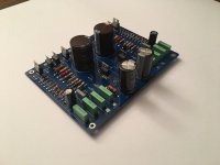
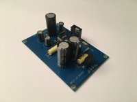
For power supply I have developped the pcb in attach, two solution of stabilized HT
One is full stereo and one is more simple.
With Fet , they are very stable and the ripple is almost zero.
Walter
the pcb is on the way.It will be stereo
I will post the proto when available.
The Bax is passive.
Point to point is not very complicate, just a little of attention.
For power supply I have developped the pcb in attach, two solution of stabilized HT
One is full stereo and one is more simple.
With Fet , they are very stable and the ripple is almost zero.
Walter
Attachments
I assume you mean the tone controls are passive. 'The Bax is passive' is a contradiction in terms.
to ejp.
The Baxandall original circuit was defined from the author "Negative feedback tone control"
Wireless world, October 1952.
There is a variation:
The James-Baxandall Passive Tone-Control Network
The James-Baxandall Passive Tone-Control Network
I have re-arrange the values of passive components to put them in the circuit.
On my post 21 the "Bax is passive" can be modified in " James-Bax passive tone control", no problem; I mentioned this variation on my article on Audioreview magazine.
Walter
Hi
the pcb is on the way.It will be stereo
I will post the proto when available.
The Bax is passive.
Point to point is not very complicate, just a little of attention.
For power supply I have developped the pcb in attach, two solution of stabilized HT
One is full stereo and one is more simple.
With Fet , they are very stable and the ripple is almost zero.
Walter
Walter excelent! Do you have the schematics or pcb layout for these Power boards? How many volts this project needs?
I gonna start to experiment on this project, what do u suggest for the capacitors? Polypropylene? Any Brand?
Thank you!
Hi
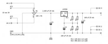
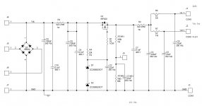
The HT is around 200-210 vdc.
If you use a stab with solid state, the Vac must be around 200-210 volt in input.
In attach the diagram of the simply ht regulator.
use a 105° cap electrolytic + some bypass as circuit.
It works fine.
You can find in attch also power for filaments
In next future I will have some pcb available
Walter
Attachments
Last edited:
Hi
The HT is around 200-210 vdc.
If you use a stab with solid state, the Vac must be around 200-210 volt in input.
In attach the diagram of the simply ht regulator.
use a 105° cap electrolytic + some bypass as circuit.
It works fine.
You can find in attch also power for filaments
In next future I will have some pcb available
Walter
Great i gonna study the schematics and get back to you soon.
Any suggestion for the capacitors in the preamp and tone control?
Thanks

FWIW - another circuit suggestion
Built it - sounds very good. Roughly 6dB Boost/cut
Charles
Very Nice! Thank you!
FWIW - another circuit suggestion
Built it - sounds very good. Roughly 6dB Boost/cut
Charles
Charles,
Let me see If i understand this well.
That section in the left is the "A" section of each Band of equalizer right? One 12ax7 for each Band. Then the "B" would be some kind of preamp stage, and "C" is the Power supply, am I right?
I supose is possible to use diferent brands of 12ax7 for each Band and get diferent colors for each frequency range. Very Nice indeed!
Did you build this point-to-point or did some pcb?
Do you have pictures of your equalizer? I would like to see How you have built It.
Thanks!
to ejp.
The Baxandall original circuit was defined from the author "Negative feedback tone control"
Wireless world, October 1952.
There is a variation:
The James-Baxandall Passive Tone-Control Network
The James-Baxandall Passive Tone-Control Network
This is not a 'rearrangement'. The James tone control precedes the Baxandall tone control by several years: to be specific, Wireless World February 1949; and contains no negative feedback whatsoever. The so-called 'James-Baxandall tone control' is a modern fiction, and an historical anachronism.
Hi
ok, if you want we can call it in another way. No problem.
I wrote that I have re-arranged the values of components mainly to find the way to use the pot 100kohm linear. In the mid position the response is completely flat.
And the variation in +/- dB is not very great but enough for a correction (if needed); the +/- 20 dB in not realistic in a domestic installation.
And it works fine, also after some listening tests with tone control on or off the results are good.
Walter
FWIW - another circuit suggestion
Built it - sounds very good. Roughly 6dB Boost/cut
Charles
Please someone could help me to understand this schematic? Schematics post #28
This is a mono equalizer right? For a stereo version I have to build two.
I don´t understand why on figure 3: session B there is an +Input and -Input. Could someone explain this to me? Those are the audio inputs right? In a unbalanced circuit I didn´t expect to see + and - input.
Thanks!
Last edited:
Ok Sorry, I believe I Just figured out How It does work.
It shows a mono equalizer but can be doubled sharing the tubes, that can deal with two channels each, am I right?
Something that is not completely clear to me is In the Power supply. Does the schematic show two power transformers? One to deliver the 150v, and other for the filaments 6.3v.... Is that right? Does this circuit run in DC Power?
multisim — ImgBB
I´m doing some experiments on the suggested schematics. I´m using multisim to simulate the circuit. I made with one band only, for testing... Seems to be working but I don´t know how to measure properly. Could someone give me some tips on how to do the righ measures in multisim?
the circuit was made to give 12db boost/cut. What should I change to make this 6db?
thanks
Last edited:
The fiction of the 'James-Baxandall tone control' appears to be solely due to one single EE assignment paper from Peru. It is otherwise very well written, and a good exercise in analysis, but Baxandall has nothing to do with it and should not have been cited or even mentioned, and E.R. James should have been cited as per above. Peruvian author is not contactable, I have tried.
I never understand why people still use passive tone controls. There is no setting that I can discover where they are perfectly flat. Only the Baxandall and other feedback-based ones like Doug Self's can do that. And there is the 20dB insertion loss.
I never understand why people still use passive tone controls. There is no setting that I can discover where they are perfectly flat. Only the Baxandall and other feedback-based ones like Doug Self's can do that. And there is the 20dB insertion loss.
As you see on my test in the center is perfect flat.
In addition, the loss is less than 20dB.
In addition in my solution you can insert or no the tone control without any changes on circuit, just one jumper per channel.
The use of 100k lin pot is more simply instead the highest value
There is only a changes on amplification.
Also you can swap the 6N6 or ECC88 as you need.
Las but not least, is more "audiophile" without feedback
🙂
Regards
Walter
to ctechdx
Excuse it is clear that you have not a big experiences on this type of job.
Is much better you use a schematic tested and meauserd on lab and more simply to build instead to work with simulations.
Walter
Excuse it is clear that you have not a big experiences on this type of job.
Is much better you use a schematic tested and meauserd on lab and more simply to build instead to work with simulations.
Walter
Thought it would be worth sharing this thread: Active Bax Preamp - review request
This was developed using the tips from Merlin's hifi book. I made the schematic in post 19 and have spare PCBs available if interested.
I've been using it for the last 3 years to great success.
This was developed using the tips from Merlin's hifi book. I made the schematic in post 19 and have spare PCBs available if interested.
I've been using it for the last 3 years to great success.
- Home
- Amplifiers
- Tubes / Valves
- Tube tone control baxandall