"Happy families are all alike; every unhappy family is unhappy in its own way." -Tolstoy
Very first thing, always: Remove anything connected to the inputs. Make a pair of shorted plugs and install. Still hum? If so, you know that the issue is inside your machine. If not, there's a common ground back at your source that you'll need to deal with.
Second thing: get back to us, and we'll go from there.
All good fortune,
Chris
I have connected the 2 point grounds, 2 channel circuit and power circuit, and didn't make a difference. Same hum is audible.
Maybe surprisingly, almost all hum problems caused by wiring are from too many "ground" connections, rather than too few. One and only one path, and don't share paths any more than you can keep from it.
All good fortune,
Chris
I did some reading on grounding and redesigned the ground following best practices. Tested along the way trying different scenarios and the hum was worst or the same.
The only thing that made it better is something that I believe it should not be done. I connected both channels tube plates to the same power filter circuit. This has brought the hum to be almost inaudible. Playing a record didn't seem to affect the volume or sound quality from before this change. The voltages on the plates dropped by 24v (5842), 40v (6n1p-1) and 47v (6n1p-2). Is it a problem running it like that? Also both channels were very balanced as well.
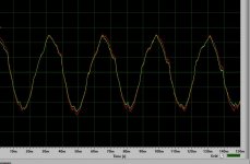
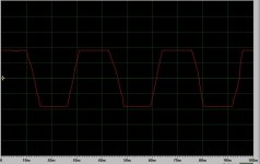
The hum is weird since it's 30Hz...... 30.5 Hz to be exact. I only have a computer scope but I was able to replicate that same sine using a signal generator set at 30.5Hz. I googled and it's not very common. I found one incident on this site regarding this 30Hz hum.
I'm attaching a pic with the sine wave from the scope. Is was taken with individual power filter circuit for each channel, the proper way. The inputs were shorted.
Thanks
The only thing that made it better is something that I believe it should not be done. I connected both channels tube plates to the same power filter circuit. This has brought the hum to be almost inaudible. Playing a record didn't seem to affect the volume or sound quality from before this change. The voltages on the plates dropped by 24v (5842), 40v (6n1p-1) and 47v (6n1p-2). Is it a problem running it like that? Also both channels were very balanced as well.
The hum is weird since it's 30Hz...... 30.5 Hz to be exact. I only have a computer scope but I was able to replicate that same sine using a signal generator set at 30.5Hz. I googled and it's not very common. I found one incident on this site regarding this 30Hz hum.
I'm attaching a pic with the sine wave from the scope. Is was taken with individual power filter circuit for each channel, the proper way. The inputs were shorted.
Thanks
Attachments
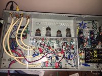
Did some more measurements and attached a couple of pics from the scope depicting 30.5Hz and 10KHz output from the tube preamp.
I don't know the technical terms but it looks like all freqs are riding the 30Hz sine as showing in the pic. What does it mean and should I be concerned about it?
My fear is that this 30Hz hum comes from the tubes and there is not much I can do about that. However, as in previous tests, connecting both channels to the same power filter (caps and plate resistors) cuts this hum amplitude by half or more. That's probably due to the plate voltages also dropping which in turn lowers the amplification. Again, I'm not sure what this means and was hoping that some smarter people could shed some light.
Attachments
A lot of folks here would like to help, but you're not giving us any useful information. To begin, we'd need a complete schematic, including all details about grounding. Drawings with a ground symbol are useless; every wire matters.
Then, rephrase your test results to date referencing the schematic. Many folks here would love to help solve this puzzle.
All good fortune,
Chris
Then, rephrase your test results to date referencing the schematic. Many folks here would love to help solve this puzzle.
All good fortune,
Chris
And please -- oscillograms are MUCH more useful *with a vertical scale*! 😉
Circuit node (and schematic reference) are also essential.
And +1, Mr Hornbeck ..
Cheers
Circuit node (and schematic reference) are also essential.
And +1, Mr Hornbeck ..
Cheers
I did a drawing of the layout that depicts the actual position of components within the chassis and the grounding path. I tried to provide as much info as possible. Hopefully it's what you're looking for.
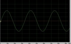
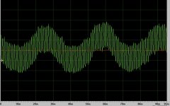
I also did some more troubleshooting and it looks like the 30Hz signal comes through from the SMPS. I've read on another forum that they can be quite noisy. I followed the signal path and it was present exiting the input tube. I disconnected the plate from the input tube as well as grid from second tube and measured after the C13 cap - the 30Hz was there. Then I disconnected everything from the SMPS, connected a 100K dummy load and with a capacitor in series the 30Hz freq was present. I attached a pic of this wave right at the PS output. The sine was amplified with a different preamp for better viewing, maybe a bit too much since it's clipping by the looks of it. Is this a good enough test or I'm out to lunch with this one?
I also did some more troubleshooting and it looks like the 30Hz signal comes through from the SMPS. I've read on another forum that they can be quite noisy. I followed the signal path and it was present exiting the input tube. I disconnected the plate from the input tube as well as grid from second tube and measured after the C13 cap - the 30Hz was there. Then I disconnected everything from the SMPS, connected a 100K dummy load and with a capacitor in series the 30Hz freq was present. I attached a pic of this wave right at the PS output. The sine was amplified with a different preamp for better viewing, maybe a bit too much since it's clipping by the looks of it. Is this a good enough test or I'm out to lunch with this one?
Attachments

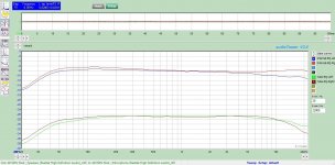
Putting aside the slight hum which I'm still working on to figure out where it's coming from, attached the the FR using a Tandberg MRL tape (320 nWb DIN) and Tandberg ferrite head part# 6480/P. I've tried a few adjustments to get the flattest response and came up with R9 @ 1KOhm and C12 @ 25.3n. I have switched the C12 with various values, including the 22n asked for in the schematic. The curves of both values are in the graph. There is a jump starting from 12.5KHz. Any idea how I can bring this down a bit?
I have tried using a 100Ohn variable resistor in place of R2 as suggested by Chris. This has flattened the curve however it increased the background noise quite a bit.
Any idea what else I can try to flatten the high freq a bit or is this the best I can do?
Thanks
I have tried using a 100Ohn variable resistor in place of R2 as suggested by Chris. This has flattened the curve however it increased the background noise quite a bit.
Any idea what else I can try to flatten the high freq a bit or is this the best I can do?
Thanks
Attachments
Hello:
I finally got some time to work on this project again. I got rid of the buzz and was able to play around with the settings and listen to results. It looks like the Internal EQ does a better job at reproducing a sweep.
Just to recap:
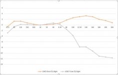
The results of the Tube EQ is not as great compared with the Internal EQ. There is significant roll of on both sides of the frequency.
The R9/R10 creates a hump between 8K-14K with a fast roll-off after that. C12 raises the curve from 1K up but it maintains the same roll-off on both ends. R13 just raises the amplitude of the curve starting from 200Hz and trending upwards afterwards. None of these components changes the low freq roll-off.
I have attached the FR of both internal EQ and Tube EQ for your reference. Any suggestions as to what can be changed to flatten the roll-offs is greatly appreciated. Unfortunately I don't know enough to figure it out myself.
Thanks again for all your help.
I finally got some time to work on this project again. I got rid of the buzz and was able to play around with the settings and listen to results. It looks like the Internal EQ does a better job at reproducing a sweep.
Just to recap:
- Tandberg 10XD deck, recapped and biased for Scotch 226, NAB EQ
- Build Mikkel Simonsen schematic as displayed above
- Made R13, C12, R9 and R10 variable/switchable in order to play with the settings
The results of the Tube EQ is not as great compared with the Internal EQ. There is significant roll of on both sides of the frequency.
The R9/R10 creates a hump between 8K-14K with a fast roll-off after that. C12 raises the curve from 1K up but it maintains the same roll-off on both ends. R13 just raises the amplitude of the curve starting from 200Hz and trending upwards afterwards. None of these components changes the low freq roll-off.
I have attached the FR of both internal EQ and Tube EQ for your reference. Any suggestions as to what can be changed to flatten the roll-offs is greatly appreciated. Unfortunately I don't know enough to figure it out myself.
Thanks again for all your help.
Attachments
So what is the input impedance of your measurement setup? Could it be loading down the output and rolling off prematurely due to the 470nF output capacitor.
On the HF end of things what load impedance does the head want to see and are you close to it?
On the HF end of things what load impedance does the head want to see and are you close to it?
My measuring equipment for this graph is a laptop so I have no clue what the impedance would be. I believe the tube preamp has a higher than usual output impedance as Mikkel mentioned along with the schematic. Most likely not a good match for the laptop.
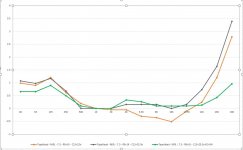
So I did a sweep manually using an VTVM for both Deck EQ and Tube EQ. I believe this graph is more accurate based on what I hear. Deck EQ a bit bright (probably a bias thing) and tube EQ too dull in upper range.
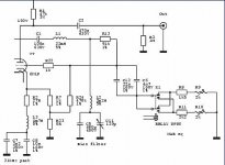
Regarding the head, I have no idea what the load impedance it expects. Can this be established from the 10XD schematic? I'm also attaching the head input schematic of 10XD in case it helps.
Thanks
So I did a sweep manually using an VTVM for both Deck EQ and Tube EQ. I believe this graph is more accurate based on what I hear. Deck EQ a bit bright (probably a bias thing) and tube EQ too dull in upper range.
Regarding the head, I have no idea what the load impedance it expects. Can this be established from the 10XD schematic? I'm also attaching the head input schematic of 10XD in case it helps.
Thanks
Attachments

Hi dromichet,
Looks like the head is expecting about 94k ohms, ignoring the small capacitance of the FET inputs. You might try replacing R16, C18, R21 with a 100k to ground as the load for the tape head, and skipping the 100nF coupling capacitor. That cap could be a little light, contributing to your low-end roll off, by the way; and the current load is about 53k ohms.
Other members here are a lot sharper than me on such things, but I would try to keep in mind that a 3-stage amp often has 4 coupling capacitors, and the low frequency roll-off total, is the sum of all four capacitor/load-resistance values. Maybe pick the one with the highest cutoff, increase its capacitor, and see if that makes a difference. Then repeat if still unsatisfactory.
The HF loss I would say 'is catastrophic', judging from the VTVM measurements you posted. But it does look a lot worse due to the change in H-scale (from the bottom 6 octaves to the top octave-and-a-½). I'd recommend maintaining the same scale across the whole graph: If 1-octave values are good enough for the bottom 7 octaves, don't splice in a couple of 2/3-octave data points, then fit in 6 values within the top octave. If you scale back the top octave, it looks at least somewhat better. 😉
Cheers
I suppose this thread is about the playback amplifier only, measured from a calibration tape.
I recommend you measure the playback amplifier first with a signal generator and a VTVM that is known flat in the audio band. I would measure it first with the IEC equalization disabled, just to be sure that the amplifier is flat in itself. If it is measured flat then you can re-apply the equalization and measure from the calibration tape.
Disabling the EQ can be done by removing the capacitors (C6, C12, C7, C8 ?) in the EQ circuit.
Thanks guys. I will work on your suggestions this weekend and report back. Based on the comment coming from the circuit developer, could you please confirm that just by disconnecting C6, C12, R8, R9 is actually removing the NAB EQ making the EQ somewhat flat? Below are his comments and pics of each stage attached:
|
| I have been working on tube electronics for an old Tandberg tapedeck for some time. The original boards were all very dead - probably because of a lightning strike. At least all the transistors were dead... But instead of repairing the original electronics I thought it would be a lot more interesting to design tube electronics for it. So far the playback amp design is completed. The playback amp is a three-stage triode amp. I will describe the design spread accross a couple of pages. The circuit description is below. The part list and construction notes are on page 2. I will add measurements later. |
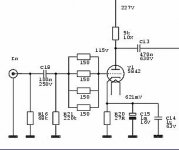
| Input Stage To the right the schematic of the first stage can be seen. The first stage uses the 5842 triode (also known as WE417A). The 5842 has a very high transconductance (around 25mA/V), and is very low in noise. The stage has a flat frequency response and a gain around 35 times. The four 150 Ohm resistors are grid stoppers that are there to prevent oscillations. The 5842 has four grid connections, and it's necessary to use a grid stopper on each pin. As can be seen from the voltage figures, the current is quite high at about 22mA. That increases the transconductance of the tube and lowers the noise. But the power dissipated by the tube is only around half the rated power, so tube life should be fine. |
| Second Stage And here is the second stage. As the first stage this stage is also "just" an amp stage with a flat frequency response, but this time the gain is lower at around 25 times. The second stage uses half of the 6N1P double triode. The 6N1P is a medium mu triode with higher transconductance and mu than the "standard" tubes like ECC82 and 6SN7. The 6N1P also offers low distortion (and a great price), which makes it a good choice IMHO. |
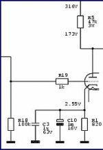
The third stage is where most of the "interesting" stuff happens. All the filters are placed in this section. The amp in this section is the other half of the 6N1P. The stage is similar to the second stage. One difference is that the cathode resistor R2 is not decoupled by a big electrolytic cap. Instead there is a series resonant filter consisting of L3, C7 and C8 that resonates at 21kHz. This creates a small peak in the frequency response around 21kHz, that is there to compensate for losses in the playback head. The resistor R2 decreases the Q of the filter making the peak less sharp. The second filter is the bias filter. This filter is placed between the second and third stage and consists of the parts L1, L2, C5 and C11. It creates are lowpass filter that removes any residual bias signal from the tape, to avoid problems like high-frequency instability in the following amp. The lowpass frequency can be adjusted by the trimmer C11. The -3dB frequency can be adjusted between 35 and 40kHz. The third filter creates the NAB eq (de-emphasis). It consists of the parts R13, C6, C12 and either R8+R9 or R10+R11. This filter creates a low pass that becomes active above 50Hz and "stops working" around 4kHz. The high frequency part can be adjusted by the trimmers R9 and R10. The reason there's two of them is to provide settings for two different speeds. In my case I will need 3.75 and 7.5ips. The frequency response probably won't be perfect at 3.75ips, but since I only have old tapes recorded at that speed, I don't care much about that. By making the 21kHz peak filter switchable the response could easily be made perfect though. 15ips uses the same eq as 7.5ips, so 15ips should work just fine - I don't have any decks to test that with though. The output is taken from the plate (anode) of stage three. That makes the output impedance quite high, so the input impedance of the following preamp or poweramp should be 100kOhm or higher. Is that is not possible (or if long cable runs are needed) a buffer stage like a cathode follower should be added. I will probably add one later. |
Attachments
To answer your first question, only C6 and C12 need to be disconnected; R8 and R9 may remain connected.
That leaves two L / C filters largely undamped: L1 / C1 and L5 / C5+C11. The schematic says the latter is a bias trap so it may not cause a problem at the lower frequencies you're probably measuring.
The L1 / C1 is another story. I have no idea what a 3k4 series-resonant filter is doing in that position, or how it could possibly work without some value of resistor in parallel (in series with a coupling cap, to scrape off the Plate voltage) to pass signals outside of the likely-rather-peaky resonance. Hopefully some of the smarter folk on here can sharpen me up! 😱
You can try fixing the overall gain (for test purposes) at approximately the original circuit's 1kHz value, by substituting a resistance of about 5k96 in place of C6+C12 -- 6k8 and 47k in parallel is pretty close. That's the reactance of 26,7nF at 1kHz. Without some such or similar mechanism I would expect some pretty wild results.
The remainder of your plan will take me a while to soak up. I don't know enough HTML to sort out these bits, for example:

Cheers
That leaves two L / C filters largely undamped: L1 / C1 and L5 / C5+C11. The schematic says the latter is a bias trap so it may not cause a problem at the lower frequencies you're probably measuring.
The L1 / C1 is another story. I have no idea what a 3k4 series-resonant filter is doing in that position, or how it could possibly work without some value of resistor in parallel (in series with a coupling cap, to scrape off the Plate voltage) to pass signals outside of the likely-rather-peaky resonance. Hopefully some of the smarter folk on here can sharpen me up! 😱
You can try fixing the overall gain (for test purposes) at approximately the original circuit's 1kHz value, by substituting a resistance of about 5k96 in place of C6+C12 -- 6k8 and 47k in parallel is pretty close. That's the reactance of 26,7nF at 1kHz. Without some such or similar mechanism I would expect some pretty wild results.
The remainder of your plan will take me a while to soak up. I don't know enough HTML to sort out these bits, for example:
Cheers
I think C1 is just a coupling capacitor. sqrt(L1/C1) is only 469 ohm, so the series resonant circuit L1 C1 will be very overdamped by the output resistance of the previous stage. That is, it's essentially a coupling cap and inductor rather than a resonant circuit.
Don't ask me why you need inductor L1 in the first place, as I haven't a clue.
Don't ask me why you need inductor L1 in the first place, as I haven't a clue.
Regarding L1/C1 these are the designer comments:
The second filter is the bias filter. This filter is placed between the second and third stage and consists of the parts L1, L2, C5 and C11. It creates are lowpass filter that removes any residual bias signal from the tape, to avoid problems like high-frequency instability in the following amp. The lowpass frequency can be adjusted by the trimmer C11. The -3dB frequency can be adjusted between 35 and 40kHz.
For testing purposes, I disconnected C6, C12, R8, R9 from the circuit. I've also disconnected L2,C5,C11. I fed a sweep 20 to 20KHz and below are the results:
The cathode resistor R2 is not decoupled by a big electrolytic cap. Instead there is a series resonant filter consisting of L3, C7 and C8 that resonates at 21kHz. This creates a small peak in the frequency response around 21kHz, that is there to compensate for losses in the playback head. The resistor R2 decreases the Q of the filter making the peak less sharp.
I'm not sure if these tests are any help
The second filter is the bias filter. This filter is placed between the second and third stage and consists of the parts L1, L2, C5 and C11. It creates are lowpass filter that removes any residual bias signal from the tape, to avoid problems like high-frequency instability in the following amp. The lowpass frequency can be adjusted by the trimmer C11. The -3dB frequency can be adjusted between 35 and 40kHz.
For testing purposes, I disconnected C6, C12, R8, R9 from the circuit. I've also disconnected L2,C5,C11. I fed a sweep 20 to 20KHz and below are the results:
- At C13 it's flat across the spectrum
- At C1 it's flat until 12K and slowly rising to +1db at 20KHz so I guess it would also be considered flat
- At C2 (output), it's flat to about 4K and slowly rising to +3db at 20KHz. Is this caused by the L3,C7,C8? These are the designer comments regarding these:
The cathode resistor R2 is not decoupled by a big electrolytic cap. Instead there is a series resonant filter consisting of L3, C7 and C8 that resonates at 21kHz. This creates a small peak in the frequency response around 21kHz, that is there to compensate for losses in the playback head. The resistor R2 decreases the Q of the filter making the peak less sharp.
I'm not sure if these tests are any help
After the above test, I also removed L3,C7,C8 and placed a 4700u (the only one I had) in parallel with R2. After that, the FR was flat to 4K and slowly decreasing to -2db at 20KHz. I'm assuming the R7 and R24 still connected are causing this drop.
Are these tests valid to check if the circuit provides a relative flat response without the EQ in place?
Are these tests valid to check if the circuit provides a relative flat response without the EQ in place?
- Home
- Amplifiers
- Tubes / Valves
- Tube tape repro head preamp for Tandberg TD20/10XD Reel to Reel