Yes.dromichet said:Are these tests valid . .
No. Generally speaking resistors do not cause upper treble rolloff in those circuit positions.dromichet said:I'm assuming the R7 and R24 still connected are causing this drop.
A reporting tip, if you can stand it: Since capacitors often DO affect frequency response, measure at the Plate if the capacitor is the coupling to the next stage. Saying for example:
is ambiguous, since the input side is likely different than the output side.At C1 it's flat until 12k . .
Since you have the benefit of the designers' explanation of the circuit's function, maybe consider neutralizing only the NAB EQ. If the compensation is for tape head limitations, or other factors that are not related to NAB equalization, leave them in. Bypassing a 27 ohm Cathode resistor with a 4700uF electrolytic is likely to be misleading if the 'bypassing' was precisely R2, which would increase the effect of the 21kHz peaking filter. From your description, it sounds like you went Cathode to Ground (which I would call 'correct'), eliminating the 21kHz peaking; but you still have the 4700uF capacitor's shortcomings, which may not be insignificant compared to R2's value, 27R.
Best Regards
Thanks Rick for the information. If I understand it correctly, I should leave the Bias filter (L1,L2,C5,C11) and 21KHz peak filter (L3,C7,C8) connected and only disconnect the NAB EQ (C6,C12,R8,R9). I also understand that the playback head has an impact on the FR as well as the coupling caps, therefore I've done 2 more tests, both of them with the EQ disconnected.
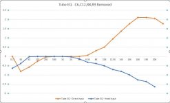
In first test, I've connected the signal generator to the input of the tube eq to get a reference of the preamp FR without the playback head involved.
In second test, I've connected the signal generator to the playback head as described in the Tandberg manual and run a sweep.
I've attached the FR of both results. The head definitely has an impact and I'll need to play around with some components values. First, I will try your suggestion of replacing R16, C18, R21 with a 100k to ground as the load for the tape head, and skipping the 100nF coupling capacitor, unless you have other suggestions based on the last test.
Thanks
Attachments
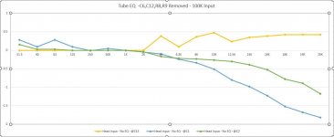
Did some more testing. This test includes Rick's suggestion of replacing R16, C18, R21 with a 100k to ground as the load for the tape head, and skipping the 100nF coupling capacitor. This did boost the low 30Hz by one db. Not sure I'll need it once I'll figure out the high freq drop. The rest of the testing is with the test point behind each coupling cap, after each stage, with the signal fed at the tape playback head. According to the results as seen in the graphs, it looks like the high freq gradual drop after 4K happens at 2nd stage at C1.
I will tinker a bit with the values of C1 to see if it makes any difference. Do you have any suggestions based on these results?
With the signal fed into the head as per Tandberg's instructions, is my goal to bring the FR as flat as possible without the NAB EQ circuit attached? Once that's achieved, attach the eq and tinker with the eq values to match the NAB curve? Is my thinking correct or am I way off?
Thanks
Attachments
It looks like I'm a bit over my head on this project as it seems to be all about the tape playback head. This design seems to be specific to the designer's Tandberg reel to reel but he doesn't specify which model.
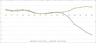
I've run the NAB MRL tape on 2 Tandberg decks: 10XD and 20TD. Both of them have different FR running through the tube preamp which indicates that the head is the deciding factor. Unfortunately I don't have the knowledge to compensate for the different heads.
I've run the NAB MRL tape on 2 Tandberg decks: 10XD and 20TD. Both of them have different FR running through the tube preamp which indicates that the head is the deciding factor. Unfortunately I don't have the knowledge to compensate for the different heads.
Attachments
(responding to post #43) Fairly reasonable -- to me at least. 😉
L1 is likely causing the remaining rolloff, but is fairly slight. But since it is designed to contribute to the NAB EQ, you could temporarily place a 1k or 2,2k resistor in parallel with it, reducing its effect.
Magnetic tape, even at higher performance levels, is inherently 'less flat' than newer mechanisms. The V-scale of the graph is making the performance look much worse than it really is. The gold curve fits within ±¼dB, the green within ±½dB, and the audible/reproducible portion of the blue trace -- up to 16kHz -- is within ±¾dB. I don't remember a consumer deck that could do better. (Doesn't mean there isn't one . .)
I bet if you draw those graphs more conventionally, feeling inspired will come more easily than it does now.
Best Regards
(responding to post #44) Well, darn -- here I was thinking we were getting reasonably close. So . . was this with the NAB EQ turned back on?
Sure do like this vertical scale better. Hopefully some of the sharper-than-me folks on here are ready to pipe in, 'cause that's a whopping big difference between models(!), and I'm pretty sure it's above my pay grade. I'm reduced to experimenting with head load resistors. Maybe even put the 68k, 100n coupling, and 220k grid resistor back in for starters.
Also, need to correct myself -- I gave wrong advice: The coupling capacitor prevents even small grid leak currents -- or larger valve mishap currents -- from causing head magnetism. Best put it back in.
Cheers
Hi Rick, you last post refers to post #43? The graph is with the nab eq removed. Just the tape head and the rest of the circuit which is supposed to be quite flat, which it somewhat is.
The moment i connect the nab eq circuit than i get the crappy results which seem to be very dependent on the tape head. The question is how do i compensate for it.
The moment i connect the nab eq circuit than i get the crappy results which seem to be very dependent on the tape head. The question is how do i compensate for it.
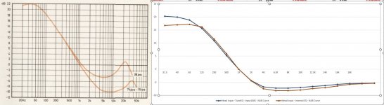
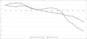
Here is another weird thing. One of the EQ test in the Tandberg service manual is to run a sweep against the playback head and check the response of the EQ output against their FR graph. This test is in case I don't have an MRL test tape. The weird thing is that performing this test, both the internal EQ and the tube EQ has very similar performances. I'd say the tube eq is an even closer match to their graph. See first pic.
However, playing an actual MRL tape or recorded tape has total different FR between internal and tube EQ. The MRL is not good for this but use it as reference. See pic 2
However, playing an actual MRL tape or recorded tape has total different FR between internal and tube EQ. The MRL is not good for this but use it as reference. See pic 2
Attachments
- Home
- Amplifiers
- Tubes / Valves
- Tube tape repro head preamp for Tandberg TD20/10XD Reel to Reel