I am looking to design a low parts count tube sound simulating circuit using JFETs.
From what I understand, the idea is to inject 2nd order harmonics into the original signal. And from my research JFETs are the best alternative as they behave similarly in distortion profile to a tube, but don't require all of the tube circuitry overhead.
I am not doing EE as a profession so looking for a second opinion on the circuit that I have came up.
As a basis I took circuit from ESP article - https://sound-au.com/articles/followers.html
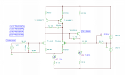
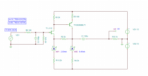
It is long tail pair of JFETs with pnp BJT providing feedback. I added current mirror to fix the offset. Also added compensation components. It runs fine in simulator but I wonder if there is something that needs to be accounted for that cannot be simulated.
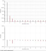
I was shooting for a distortion of 0.01% with full voltage swing at the input of 2Vrms (or 2.82Vp). For that I added 330R resistor to the emitter of the feedback transistor and I assume it will reduce the "extent" of the feedback, thus allow for more nonlinear behavior (more distortion).
Tubes produce around 0.1% 2nd harmonic distortion so I am wondering if I should come up with circuit that makes that much? Or 0.01% is enough lol?
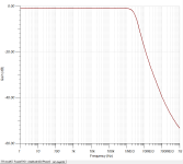
Attached are simulation files.
Any comments are welcome! 🙂
From what I understand, the idea is to inject 2nd order harmonics into the original signal. And from my research JFETs are the best alternative as they behave similarly in distortion profile to a tube, but don't require all of the tube circuitry overhead.
I am not doing EE as a profession so looking for a second opinion on the circuit that I have came up.
As a basis I took circuit from ESP article - https://sound-au.com/articles/followers.html
It is long tail pair of JFETs with pnp BJT providing feedback. I added current mirror to fix the offset. Also added compensation components. It runs fine in simulator but I wonder if there is something that needs to be accounted for that cannot be simulated.
I was shooting for a distortion of 0.01% with full voltage swing at the input of 2Vrms (or 2.82Vp). For that I added 330R resistor to the emitter of the feedback transistor and I assume it will reduce the "extent" of the feedback, thus allow for more nonlinear behavior (more distortion).
Tubes produce around 0.1% 2nd harmonic distortion so I am wondering if I should come up with circuit that makes that much? Or 0.01% is enough lol?
Attached are simulation files.
Any comments are welcome! 🙂
Attachments
If you want to simulate a tube circuit then I would make it damn simple like a tube circuit, ie one JFET wired like a (~12AX7) tube with RC coupling and no feedback. The feedback of your circuits is "cleaning up" the distortion that you're after.

The idea is to do sound simulation only, not exact tube circuit replication using JFETs. I think there are many already made.
It leads me to idea though - should I put variable pot instead of 330R resistor to control the "depth" of the "tube simulation" applied?
It leads me to idea though - should I put variable pot instead of 330R resistor to control the "depth" of the "tube simulation" applied?
@ gooduser:
"...exact tube circuit replication using JFETs. I think there are many already made..."
Really? If you can find them, you're an expert. I've counted two sofar, and extremely elaborous with rare components (P-ch J-fet & P-ch depletion MOSfet's, or a diode-resistor ladder network of over 16 sections, along with opamps and additional supplies and grounds).
"...should I put variable pot instead of 330R resistor..."
As far as clipping to the current mirror saturation level permits.
In general: how do you know for sure your circuit sounds like a tube if you add 2nd harmonics?
You claim is that if a tube produces 2nd harmonics, adding 2nd harmonics to a (semi-) circuit yields a tube-sound?
Second law of thermodynamics rules always.
Here is one circuit - http://www.runoffgroove.com/fetzervalve.html
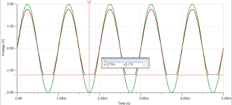
I attempted to use a simple J112 jfet voltage follower, but it does not swing below negative 2.smth volts. It also produces too much distortion.
I attempted to use a simple J112 jfet voltage follower, but it does not swing below negative 2.smth volts. It also produces too much distortion.
Attachments
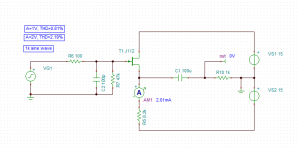
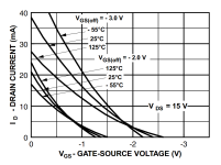
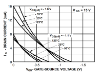
It all depends on the Id-Vgs plot for this jfet, in this circuit. With 2mA, it can be close to Idss, so clipping/reverse bias can occur... mostly occuring at positive volt?Here is one circuit - http://www.runoffgroove.com/fetzervalve.html
I attempted to use a simple J112 jfet voltage follower, but it does not swing below negative 2.smth volts. It also produces too much distortion.
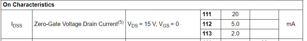
Add a complete datasheet for the J112 to avoid annoyances (I have it somewhere, searching, things... include, instead of guesses).
What is "2.smth volts"?
Well, of course, 2mA into 1k is 2V. If you want 15V into 1k then you need 15mA. Tube amps rarely use cathode followers. The sound you want comes from common cathode (source) stages. To avoid gain, you just use a small drain load resistor. If you want to drive 1K, since most JFET Idss is less than 15mA you will need to buffer it.
I was going to mention that a bootstrapped BJT EF also creates 2nd order harmonics, provided that the source is hi-Z. This makes a great guitar input because it is also hi-Z, very important for inductive pick-ups.
If you want a general-purpose 2nd order distortion, I suggest an analog multiplier squaring circuit, and vary the amplitude of one of the inputs. It's called a "Gilbert cell". You just drive both the LTP and the emitter (source) current source. In your case, you don't want a "4 quadrant multiplier", just two, or less.
https://www.analog.com/media/en/training-seminars/tutorials/MT-079.pdf
That's what is considered as a video amplifier (R5 can be omitted, adjust R3), known from the early seventies.Adding BJT buffer helps to extend input/output swing to +-6V and reduces distortion.
High gain, high frequency, high feedback, a precision amplifier. No tube perfermance though.
Briliant!Well, of course, 2mA into 1k is 2V. If you want 15V into 1k then you need 15mA. Tube amps rarely use cathode followers. The sound you want comes from common cathode (source) stages. To avoid gain, you just use a small drain load resistor. If you want to drive 1K, since most JFET Idss is less than 15mA you will need to buffer it.
I was going to mention that a bootstrapped BJT EF also creates 2nd order harmonics, provided that the source is hi-Z. This makes a great guitar input because it is also hi-Z, very important for inductive pick-ups.
If you want a general-purpose 2nd order distortion, I suggest an analog multiplier squaring circuit, and vary the amplitude of one of the inputs. It's called a "Gilbert cell". You just drive both the LTP and the emitter (source) current source. In your case, you don't want a "4 quadrant multiplier", just two, or less.
https://www.analog.com/media/en/training-seminars/tutorials/MT-079.pdf
Learned something: Gilbert cell. I'm diving into it! Thanks steveu!
Interesting.If you want a general-purpose 2nd order distortion, I suggest an analog multiplier squaring circuit, and vary the amplitude of one of the inputs. It's called a "Gilbert cell". You just drive both the LTP and the emitter (source) current source. In your case, you don't want a "4 quadrant multiplier", just two, or less.
https://www.analog.com/media/en/training-seminars/tutorials/MT-079.pdf
Member
Joined 2009
Paid Member
I thought it's been common wisdom around here that injecting 2nd harmonic is not sufficient to give an amplifier 'tube sound'. Any single ended amplifier can pull off the 2nd harmonic trick. There's the matter of output impedance - speaker interaction that can be as, if not more, important. But that's not to say that a 2nd harmonic JFET circuit won't be a very rewarding project and worthy of the effort indeed.
Be careful with the minus symbol when addressing junction field effect transistors!Here:
J112 graphs + clips at -1.72V actually. Need it to go to at least 2.82V.
You need to go to (minus =) -2.82V?
And given the spread of these 'qube-formula' components, that's only a meager factor 1.6 off.
Those graphs show also an Idss of 8-16mA and a 20-40mA in the Vpo range between -1.1 to -3.0V (3/1.1≈ 2.7)--((Notice √2.7 ≈ 1.6!)).
In the circuit of #5, limitations are depending on the given model (when simulating with defined parameters), or on the actual specifications per unit. A very dreadfull route and rarely used in the industry. The #6 circuit is very widely used as a reliable solution. There's much to find about this in the Siliconix & Teledyne handbooks (era 1978-1981).
It's a bit of my issue, and I do not believe in the 'injection' method:Interesting.
https://www.diyaudio.com/community/...hat-makes-no-sense-at-all.395836/post-7354347
Have a look at this paper by Nelson Pass.
He shows how to create 2nd harmonic.
https://www.firstwatt.com/pdf/art_diy_preamp_h2v2.pdf
He shows how to create 2nd harmonic.
https://www.firstwatt.com/pdf/art_diy_preamp_h2v2.pdf
Driving the fet into the ohmic region, et voilá, 2nd harmonics. Can also be applied to mos (sharp) and bjt (sharper).
No so impressive.
No so impressive.
If one does not provide enough second harmonic, use two...
http://www.hawestv.com/mtv_faq/faq_fetpreamp5.htm
http://www.hawestv.com/mtv_faq/faq_fetpreamp5.htm
- Home
- Source & Line
- Analog Line Level
- Tube sound simulating circuit using LS844 matched JFETs need help