If valve amp designers of the day could see the sort of conversations people would be having in 2012 they would have all died of laughter
This is a signal picked up by a shielded transformer 10 inches away from a power transformer radiating the diode rectifier switching noise? That looks like plain old 60Hz tranny hum like the stuff my phono cartriges pick up when they are within 2 feet of an amp.
No, it's actually radiated switching noise. 60Hz hum has no harmonics. There is 60 Hz in there also from the transformer.
All diodes have some junction charge. This holds the diode in a conducting state for a little while after the switch off threshold is crossed. Then a current spike is produced when the capacitance abruptly discharges. This is where the pulse train comes from. The current runs in the secondary of the transformer and will radiate from the winding just as the 60 Hz will.
Michael
If memory serves me correctly, Magnavox did use SS rectification towards the end of the tube amp production.
So did Marantz and many other manufacturers.
I doubt they would have done so if it impacted the sound.
So did Marantz and many other manufacturers.
I doubt they would have done so if it impacted the sound.
No, it's actually radiated switching noise. 60Hz hum has no harmonics. There is 60 Hz in there also from the transformer.
All diodes have some junction charge. This holds the diode in a conducting state for a little while after the switch off threshold is crossed. Then a current spike is produced when the capacitance abruptly discharges. This is where the pulse train comes from. The current runs in the secondary of the transformer and will radiate from the winding just as the 60 Hz will.
Michael
Your spectrum shows your 120v 60Hz Mains RMI level the same level as your Mu volt diode switching noise and all the associated AF harmonics.
I doubt they would have done so if it impacted the sound.
But it DID impact the sound. It improved it- lower power supply impedance so less sagging under load.
When to think a little better before grabbing drill and soldering iton, the amp can be built immune to power cables, sockets, rectifiers, motor run paper in oil herrings. Proper layout and good filtering is the key. Voltage stabilizing using SS devices and modern capacitors is cheap today, while it was unaffordable on the peak of honor of best tube amps of vintage.
To clarify my intent, I should have said "I doubt they would have done so if it impacted the sound negatively".
Your spectrum shows your 120v 60Hz Mains RMI level the same level as your Mu volt diode switching noise and all the associated AF harmonics.
It's all sub microvolt. The peaks are about 100 nanovolts equivalent input level or less.
Here's one where the 60 Hz energy is higher than the switching noise. The 60 Hz and the switching noise respond differently to diode snubbing, but it all responds to relocation and shielding.
I'm not sure the point you're trying to make about my data.
It's probably true that these issues are exaggerated in a microphone preamp vs. a power amp; at some point it depends on specifics.
Attachments

Last edited:
It's all sub microvolt. The peaks are about 100 nanovolts equivalent input level or less.
Here's one where the 60 Hz energy is higher than the switching noise. The 60 Hz and the switching noise respond differently to diode snubbing, but it all responds to relocation and shielding.
I'm not sure the point you're trying to make about my data.
It's probably true that these issues are exaggerated in a microphone preamp vs. a power amp; at some point it depends on specifics.
You had said that the 60Hz was the power tranny's own radiation. I take that to mean the main primary suppy voltage at 120v. getting to your mike input tranny. All the signatures on your plot came from that tranny radiating including the supposed diode switching uV. signals. Wouldn't you think that the primary 60Hz radiation would be sky high compared to the uV. switching noise on your spectrum?
I don't think your plot signatures can be directly linked to the diodes. Why take this "noise" sample from the input tranny and deduce it all comes from the PS diodes radiated through the air? Why not take your sample from the diodes?
If one has a 1us pulse repeating at 60Hz, then the inverted signal is a 16665us pulse at 60Hz.
😱 let's not get into the AC vs. "pulsating DC" argument again 😱
😀😀😀
Inverted or not, the spectrum is consistent with what's expected of a 120 Hz pulse train
You had said that the 60Hz was the power tranny's own radiation. I take that to mean the main primary suppy voltage at 120v. getting to your mike input tranny. All the signatures on your plot came from that tranny radiating including the supposed diode switching uV. signals. Wouldn't you think that the primary 60Hz radiation would be sky high compared to the uV. switching noise on your spectrum?
I don't think your plot signatures can be directly linked to the diodes. Why take this "noise" sample from the input tranny and deduce it all comes from the PS diodes radiated through the air? Why not take your sample from the diodes?
Oh, you 're claiming that the diode reverse recovery pulse is "microvolts"... I don't agree, and it's been studied by far more than just me. I think I'll let you go research it.
Yes it all comes from the mains toroid, radiated through the air. Both the 60 Hz, and the switching noise. It's all current in the transformer winding and all radiates much the same. I didn't just "deduce" it, I did the work of isolating it and correcting it. All my plots are relative to the amplifier output, but there was a step of verifying that the noise signal originated in the rectifier loop.
And now I think I've spent enough time on this today. Time to reflect for a while and eat some bacon...
Thanks for your attention,
Michael
Last edited:
But it DID impact the sound. It improved it- lower power supply impedance so less sagging under load.
you again....😀
i still use tube rects because i have them and i like to use them.....
Time to reflect for a while and eat some bacon...
Cholesterol! 😱😱😱
More dangerous than rectifier spikes!
i still use tube rects because i have them and i like to use them.....
Can't argue esthetic choices! 😀
No, it's actually radiated switching noise. 60Hz hum has no harmonics. There is 60 Hz in there also from the transformer.
All diodes have some junction charge. This holds the diode in a conducting state for a little while after the switch off threshold is crossed. Then a current spike is produced when the capacitance abruptly discharges. This is where the pulse train comes from. The current runs in the secondary of the transformer and will radiate from the winding just as the 60 Hz will.
Michael
Just to clarify that this is noise resulting from the rapid dI/dt occuring when the secondary winding transitions from conducting to non-conducting - and the transformer secondary leakage inductance splatters energy through alternate pathways.
It has not got anything per se to do with the reverse recovery character of the diode being used. Such reverse recovery character can indeed generate MHz ringing as a function of the specific current waveform at that time, which is a different dI/dt impact as the diode finally stops conducting current. Different diodes (eg. 1N4007 and UF4007) will have this different character. But this character is not what is is shown in Michael's spectrum plots.
you again....😀
i still use tube rects because i have them and i like to use them.....
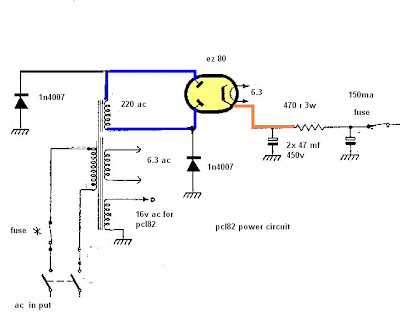
how is the general methode of Vout calculating for this hybrid rectifier (diode and tube) ?
ex: I've got transformer with 260Vac out, using 2 diode and 1 GZ34 tube like above schema; how much is the V+ out in case of total current of 120mA ?
Tks,
Last edited:
how is the general methode of Vout calculating for this hybrid rectifier (diode and tube) ?
ex: I've got transformer with 260Vac out, using 2 diode and 1 GZ34 tube like above schema; how much is the V+ out in case of total current of 120mA ?
Tks,
looking at GZ34 datasheet, http://www.wooaudio.com/docs/tube_data/5AR4.pdf
at an output of 120mA, you lose about 10volts on each rectifier plate, losses on the silicon diodes are too small so i just ignore it.
so 260 volts, you can get about 330volts dc.....
but this is not all, the dc resistance of your power traffo drops voltage...the ac current at your traffo secondary is about 1.1 x 120mA or 132mA....
the effect is lower than 260volt input to the rectifier, so that output dc voltage is likewise lower....
Surely the dI/dt is precisely because of the diode switch off characteristic? The winding itself has not changed its conductance. A diode with no stored charge switches off slowly as the 50/60Hz voltage sweeps through zero (or around 0.6V). A diode with stored charge continues conducting until the stored charge is all gone, then it can stop very rapidly.trobbins said:Just to clarify that this is noise resulting from the rapid dI/dt occuring when the secondary winding transitions from conducting to non-conducting - and the transformer secondary leakage inductance splatters energy through alternate pathways.
It has not got anything per se to do with the reverse recovery character of the diode being used.
that of course is the case with a full wave center-tapped rectifier circuit where one half of the winding does not conduct output current...
so that by using a full wave bridge instead mitigates this problem, since the transformer secondary conducts output current the for whole of the electrical cycle.....it is said that transformer heating is less and utilization higher.....
this is the reason i stopped using center tapped full wave rectifiers a long long time ago....
Last edited:
- Home
- Amplifiers
- Tubes / Valves
- Tube Rectifiers do sound different