If minor changes to the power supply affect the sound quality so much that it can be positively identified, then the power supply is inadequate for the job. It has been marginally designed. What's the mystery if a marginal design then gets a major change that reduces its output characteristics? On the other hand, if an adequate design is "improved" is it ...really... improved?
20
20
Do not use psychological explanations for physical phenomena, please. The right are the measures, lack of them is what justifies the research.
Years ago, in Audioamateur, an engineer published a measures on rectifier diodes. In such measures, made with a spectrum analyzer, could see that diodes as 1N4002 have a noise spectrum that extends to the 4MHz, others such as Schottky generate much less noise.
The circuit used to make these measures perhaps may be adapted to measure valves (tubes).
When I moved to live in another city I donated all my technical library at the Polytechnic of my old city, so I do not have a copy of the article, but maybe someone kept his collection of Audioamateur and can put it here.
Happy days
But tube amps historically have super crappy B+ power supplies by your typical power supply standards of regulation and ripple.
Of course when the supply is modulated by the output stage signal and by it's own noise, and the amplifier has low PSRR, tweaking the supply changes the sound.
Lots of people complain about the "sound" of regulated power supplies. Go figure...
Without good measurements or objective standards it becomes practically a philosophical argument, which is particularly frustrating for those of us with hard science approach to things.
Do not use psychological explanations for physical phenomena, please. The right are the measures, lack of them is what justifies the research.
Years ago, in Audioamateur, an engineer published a measures on rectifier diodes. In such measures, made with a spectrum analyzer, could see that diodes as 1N4002 have a noise spectrum that extends to the 4MHz, others such as Schottky generate much less noise.
The circuit used to make these measures perhaps may be adapted to measure valves (tubes).
When I moved to live in another city I donated all my technical library at the Polytechnic of my old city, so I do not have a copy of the article, but maybe someone kept his collection of Audioamateur and can put it here.
Happy days
That's a great example of how results can be misinterpreted and miscommunicated.
diodes as 1N4002 have a noise spectrum that extends to the 4MHz
Saying that diodes have a spectrum is kind of like saying they have a sound, isn't it?
I'm here to tell you that diodes don't have a noise spectrum. They pretty much just sit there until put into a circuit with inductance, capacitance, energy... I'm sure that's not what the article claimed either but that's what people take away as justification for what they are hearing.
The problem of switching noise in rectifier circuits is pretty well known and has been since the first rectifiers were made. There are also well known techniques to alleviate it's effects on the supplied circuits.
But statements such as above are why people ditch their noisy semiconductor diodes in favor of nice MV rectifiers 🙄
But tube amps historically have super crappy B+ power supplies by your typical power supply standards of regulation and ripple.
...by your typical power supply standards?
If typical power supply "standards" are common engineering knowledge, then why are they all "super crappy?" It only takes a few $$ worth of parts to build a good PS. Are all of the custom builders who can build from scratch and all the "boutique" builders and all of the classic hi-fi amps... super crappy?
The problem of switching noise in rectifier circuits is pretty well known and has been since the first rectifiers were made. There are also well known techniques to alleviate it's effects on the supplied circuits.
If diode "switching" noise is audible then the diode is defective. The should be no "noise" from a diode in the audible range. All the diode "switching" noise is near the Mhz frequencies. They are small level, microsecond events. It's electronic "noise." Not audible.
...It only takes a few $$ worth of parts to build a good PS. Are all of the custom builders who can build from scratch and all the "boutique" builders and all of the classic hi-fi amps... super crappy?
Unfortunately, it takes more than a few $$, but not a lot more. It does take some attention to detail.
There's a lot of inattentive power supply design out there, especially as one moves into the boutique world. The "classic" amps were constrained by available parts in those days and, yes, cost.
The missing link here is designing circuits with high power supply rejection.
I always hear people saying audio is a series of compromises. Yet for some, when it comes to amplifier design, there is the weird myth of the perfect circuit. This is not hard science, this is fantasizing.
I am not surprised that with a given set of design choices/compromises the impact of a particular real world component makes an audible difference. Understanding this and allowing those audible differences become a tool for design may not be hard science either but I suspect good engineering.
I am not surprised that with a given set of design choices/compromises the impact of a particular real world component makes an audible difference. Understanding this and allowing those audible differences become a tool for design may not be hard science either but I suspect good engineering.
If a diode switches at 60Hz with a spike rise time of, say, 100ps then you could get noise at all harmonics of 60Hz up to around 10MHz. This range includes audio. In addition noise at, say, 3MHz will have 60/120/180Hz etc. sidebands so if the audio circuit is susceptible to RF (many are) you can hear this too.20to20 said:If diode "switching" noise is audible then the diode is defective. The should be no "noise" from a diode in the audible range. All the diode "switching" noise is near the Mhz frequencies. They are small level, microsecond events. It's electronic "noise." Not audible.
Unfortunately, it takes more than a few $$, but not a lot more. It does take some attention to detail.
There's a lot of inattentive power supply design out there, especially as one moves into the boutique world.
... but not a lot more..
Ya, my point on cost was really to say a few $$ more to build a good PS over the aforementioned "super crappy, typical, historical..." Don't use a "38" when you need a "44".
I dont know if I'm stupid or hard to understand...
What makes it so difficult... If you have the amp or preamp and use tube rectifier... just go around ebay and try to get same type (let's say you are using 5u4, the common type). If you are using RCA brand, then try to get Sovtek or EH or even China brand. This will not cost you much. After it arrives, just plug into your system and hear... I assume you buy a good rectifier, not a weak or near to the end of service life one...
Same type, same model (pick a good common sample like 5u4)... no one will say that this is B+ different, noise different, bla-bla-bla... yes there will be some different spec from different manufacturer, but as long they are same model (5u4), I believe, spec wise, the different should be at minimum... but the sound? just try...
Get back to this thread to advise some conclusion.
If you havent tried, I believe it's better to sit and listen (dont commenting something because "you think so" or "the book says so")... dont post something that you dont even try... just not wise... imo... i could be wrong tough... 😉
Thanks.
Last edited:
I've built and listened to a few hundred amps and preamps over the years- if there's a difference in sound between two rectifiers as you describe, it's always down to easily measurable differences, mostly B+ variations. Brand to brand of the same type with the same output voltage and source resistance (i.e., sag under load and ripple)? Nope, any sound difference is most likely psychological, not acoustic.
Really...
Isn't there a "typical" tube amp B+ supply, which is filtered, unregulated?
Isn't it's performance "super crappy" when measured by "modern" standards of ripple and regulation, compared with say a Xantrex lab supply or whoever makes them these days? And compared with what a solid state regulator using a few parts could do?
The point of all the handwaving is that with many of the amp builds I see there is a lot of power supply interaction with the output stage one way or another. I think it explains why to many changing the rectifier changes the sound.
If a diode switches at 60Hz with a spike rise time of, say, 100ps then you could get noise at all harmonics of 60Hz up to around 10MHz. This range includes audio. In addition noise at, say, 3MHz will have 60/120/180Hz etc. sidebands so if the audio circuit is susceptible to RF (many are) you can hear this too.
If you have an amp that is "susceptble" to RF and you hear something, then you have a detector circuit that is somehow demodulating the some AF out of it. You can't hear true RF frequencies.
If a diode switches at 60Hz with a spike rise time of, say, 100ps then you could get noise at all harmonics of 60Hz up to around 10MHz.
"Could" ... another could.
Look at the diode spec sheets and see if you still think the switching pulse signal level at 1 Mhz "could" or DOES produce harmonics that would have any significant level.
Show us a good scope shot of what you think "could" happen. If the primary 1Mhz spike is not audible there will be no other audible harmonics. They will all be super attenuated by the time you see the 60Hz signature. A 1Mhz pulse that occurs at a 60Hz rate is not a 60 cycle signal.
A diode that is not defective will not have any significant AF noise product.
If a diode switches at 60Hz with a spike rise time of, say, 100ps then you could get noise at all harmonics of 60Hz up to around 10MHz. This range includes audio. In addition noise at, say, 3MHz will have 60/120/180Hz etc. sidebands so if the audio circuit is susceptible to RF (many are) you can hear this too.
Yes. Diode switching produces a pulse train at 120 Hz (full wave)
It's a simple exercise to show that this produces a set of harmonics from 120 Hz on out.
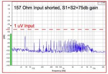
Here is an actual measurement showing the spectrum of rectifier switching noise before being corrected. It's band limited because it's being electromagnetically picked up by a shielded input transformer from an unshielded toroid power transformer some 10 inches away.
This is below the noise floor of a lot of sources (it's a microphone preamp) i.e. not usually audible but 10 dB above the noise spec. for the gear.
PS Other plots using this setup reveal that all samples of D3a ring at about 15 KHz... It's excited by lightly brushing the smooth aluminum case of the prototype unit.
Attachments
Last edited:
And aren't CFLs wonderful. They don't care about switching noise and use rectifiers that produce it. It is coupled to the AC lines, and into your amp.
So filter the incoming power as well, whether you use SS rectification or VT rectification.
So filter the incoming power as well, whether you use SS rectification or VT rectification.
My "could" was in respect of "all", not in respect of "harmonics". I only said "could" because I have learnt that any absolute statements on here can be challenged by pedants.20to20 said:"Could" ... another could.
Look at the diode spec sheets and see if you still think the switching pulse signal level at 1 Mhz "could" or DOES produce harmonics that would have any significant level.
Harmonics are certain, as you have a non-sinusoidal periodic waveform. The exact harmonics which will be present depend on the waveform, but all harmonics is actually the most likely outcome. A narrow spike may cause the harmonics to be concentrated at frequencies related to the inverse of the pulse width and rise time, but low frequency harmonics will also be present. This is simple Fourier theory.
There will, of course, also be lower frequency harmonics from the charging pulse shape (whatever the rectifier).
If by this you mean a pulse with width around 1us but repeating at 60Hz, then it will almost certainly include some 60Hz component along with many harmonics at similar levels. In this sense it is a 60Hz signal!20to20 said:A 1Mhz pulse that occurs at a 60Hz rate is not a 60 cycle signal.
And aren't CFLs wonderful. They don't care about switching noise and use rectifiers that produce it. It is coupled to the AC lines, and into your amp.
So filter the incoming power as well, whether you use SS rectification or VT rectification.
? not sure if this is in reference to my FFT plot but it's not CFLs that produced this but a 60 Hz full wave rectifier using UF4007 diodes and a relatively high DCR toroid with 3 inch leads from the toroid to the rectifier. It's powering 2 D3a filaments and about 50 mA of B+ at ~250V.
The 120 Hz pulse train produces a series of harmonics from 120 Hz on out. There is also some 60 Hz from the transformer leakage.
The noise is transmitted electromagnetically from the mains toroid to the input transformer of the mic preamp about 10 inches away. Diode snubbing, transformer relocation, and shielding were all helpful in eliminating the noise.
Michael
Attachments

Yes. Diode switching produces a pulse train at 120 Hz (full wave)
It's a simple exercise to show that this produces a set of harmonics from 120 Hz on out.
Here is an actual measurement showing the spectrum of rectifier switching noise before being corrected. It's band limited because it's being electromagnetically picked up by a shielded input transformer from an unshielded toroid power transformer some 10 inches away.
This is below the noise floor of a lot of sources (it's a microphone preamp) i.e. not usually audible but 10 dB above the noise spec. for the gear.
PS Other plots using this setup reveal that all samples of D3a ring at about 15 KHz... It's excited by lightly brushing the smooth aluminum case of the prototype unit.
This is a signal picked up by a shielded transformer 10 inches away from a power transformer radiating the diode rectifier switching noise? That looks like plain old 60Hz tranny hum like the stuff my phono cartriges pick up when they are within 2 feet of an amp.
- Home
- Amplifiers
- Tubes / Valves
- Tube Rectifiers do sound different