Hi guys,
Need some help. I'm gonna custom wind a transformer for a pair of 01A's.
The circuit requires 235v DC. Am gonna use 5AR4 rectifier for this, yes am
aware that it's an overkill but I already have them on hand. The idea is a single
supple to feed the pair of 01As via 30H 40ma choke per tube with a DCR of 615 ohms. Question, what is the AC HV voltage that is to be wound on the transformer ? Downloaded PSUD2 but am unable to get the results. Perhaps it's my ignorance
Many thanks in advance
Thks for the advice question here still arises, after being load with the 2 chokes
will the voltage drop below 230. Oh I forgot with tube rectifiers is it a 1 to 1 ratio
from AC to DC ? Been out of diy for a long time. Picking up the pieces again
Thank you again
will the voltage drop below 230. Oh I forgot with tube rectifiers is it a 1 to 1 ratio
from AC to DC ? Been out of diy for a long time. Picking up the pieces again
Thank you again
Choke, also called inductor is in simplest form a wire coil whose purpose is to make it difficult for ac signals. I cant imagine there will be voltage drop across it to worry about.
How exact is the requirement for 235v. Are you able to tweak component values to use lower dc supply, say 200v?
How exact is the requirement for 235v. Are you able to tweak component values to use lower dc supply, say 200v?
How much total current do you need?
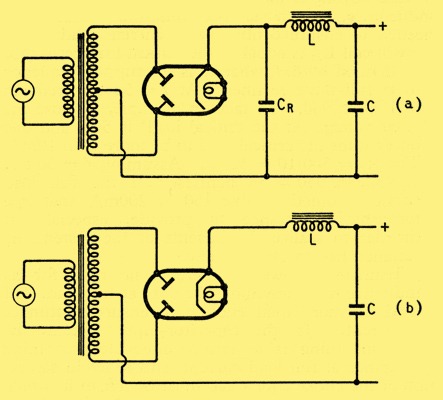
Do you intend to use a capacitor-input rectifier (a), or a choke-input rectifier (b)?
Do you intend to use a capacitor-input rectifier (a), or a choke-input rectifier (b)?
Perhaps a pseudo choke I/P filter will help, in this situation. Hybrid bridge rectify the O/P of an isolation transformer with 2X Cree C3D02060F Schottky diodes in the ground legs and a 5AR4/GZ34 in the "hot" legs.
Set the filter up as cLC. The I/P ("fudge factor") cap. needs to be held below 1 muF., in order to maintain critical current behavior. The "fudge factor" cap. tweaks the rail voltage upwards and, quite important, protects the SS diodes from inductive kick back spikes.
Don't forget a 30 Kohm bleeder resistor across each of the reservoir capacitors.
Yes Merlind I do intend to use circuit A. In reality each tube only consumes around
4 ma. From pass experience of course under higher cuurent loads, the choke does
lower voltage quite a fair bit. For this application though tube current is minimal,
the DCR of the choke that Im using will definately lower the voltage. Hence the need
for help to calculate actual voltage drop under load.
Circuit is optimize for 235 volts 02GF74.
thanks guys for the advice
Thanks Merlinb. Sorry for AC to DC using tube rectifier, is the conversion 1 : 1 ?
Also 02GF74 suggestion of making it an isolation trans does sound nice not 1 to 1 but
maybe slightly higher, would appreciate your thoughts
Thanks again
Also 02GF74 suggestion of making it an isolation trans does sound nice not 1 to 1 but
maybe slightly higher, would appreciate your thoughts
Thanks again
Thanks Merlinb. Sorry for AC to DC using tube rectifier, is the conversion 1 : 1 ?
Also 02GF74 suggestion of making it an isolation trans does sound nice not 1 to 1 but
maybe slightly higher, would appreciate your thoughts
Thanks again
The conversion from AC to DC value depends on the filter type used and the losses associated with the rectifier(s), regardless of their technology.
For cap. I/P filters, the DC voltage = (VRMS) (21/2) less losses
Forward drop in 5AR4s is comparatively small, especially when the draw is well below the 250 mA. allowable maximum.
 Discussion of direct mains operation i.e. without mains or isolation transformer is a violation of forum rules. Post deleted. Please read the rules.
I'm wondering why a DC voltage of 230V is required in an 01A based project as the maximum recommended operating plate voltage for this type is about 135V, is there some secondary regulator such as gas tubes or similar in this design?
Hi Kevin,
Kindly look at Bartola Valve webpage. It's actually a hybrid mu stage whereby
the top tube is actually a solid state device.
Looking further into rectifier tubes I now have to come back to my senses.
Guess the use of either a 6X4 or AZ1 would be more ideal in this application
Many thanks again guys
Kindly look at Bartola Valve webpage. It's actually a hybrid mu stage whereby
the top tube is actually a solid state device.
Looking further into rectifier tubes I now have to come back to my senses.
Guess the use of either a 6X4 or AZ1 would be more ideal in this application
Many thanks again guys
If the current is only 8mA total, then 170V AC will give you close to 238V DC, which sounds like what you want.
Thanks for the suggestion Eli but have no experience
Using such a circuit. How does it sound like ?
Thks
Using such a circuit. How does it sound like ?
Thks
Thanks for the suggestion Eli but have no experience
Using such a circuit. How does it sound like ?
Thks
The performance of hybrid bridge rectifiers is totally dominated by the vacuum diodes.
Hi guys,
Need some help. I'm gonna custom wind a transformer for a pair of 01A's.
The circuit requires 235v DC. Am gonna use 5AR4 rectifier for this, yes am
aware that it's an overkill but I already have them on hand. The idea is a single
supple to feed the pair of 01As via 30H 40ma choke per tube with a DCR of 615 ohms. Question, what is the AC HV voltage that is to be wound on the transformer ? Downloaded PSUD2 but am unable to get the results. Perhaps it's my ignorance
Many thanks in advance
i take it that you are winding your own power traffo...
so the first thing i calculate is the volt-ampere required by
computing for secondary power, filaments and tubes..
then the result is divided by 0.6 to get the primary VA...
from the results of calculations, you can start to wind your own...
Thanks for the suggestion Eli but have no experience
Using such a circuit. How does it sound like ?
Thks
transformer utilization is better with a hybrid rectifier than when using the full wave center tapped tube only psu...
- Status
- Not open for further replies.
- Home
- Amplifiers
- Tubes / Valves
- Tube rectifier supply help