Hello all,
I want to build a classic Mullard 5-10 EL84 tube amp and I want to use EZ81 as rectifier.But my Power Transformer has no Center Tap.It can deliver 0 - 280 - 300 - 320V@300mA , 6,3V@2A , 2 x 6,3V@4A.So I need to make an artificial center tap with 2 diodes at the anodes of rectifier tube.
Primary winding resistance is 7 Ohm , secondary winding resistance at 300V is 30 ohm.
Rs = Rsec + Nsquare x Rp where Rs = transformer effective resistance , Rsec = secondary winding resistance , Rp = primary winding resistance and N = turning ratio.
Based on this equation my power trafo has Rs = 40 Ohm --> need limiter resistors on the anodes of the EZ81 rectifier tube.
So here are my questions:
1)When you calculate the efective resistance for a trafo with no CT you consider the Rsec to be the resistance of the secondary winding as it is (in my case 30 Ohm) ? Or it is half of this because you create a center tap?
2)I want to make 2 power supplies using 2 x EZ81 (one for each channel,completely separate) feed by the same secondary of the power transformer and using one heater winding for both of them (6,3V@2A) --> this means the heaters of EZ81 in paralell and 2 x B+ from each catode.
Do you see some problems with that arrangement?
One channel for this amp need around 80mA.
Thanks in advance for your opinion.
The EZ81/6CA4 can handle up to 150 mA. Using a rectifier for each channel is good. Now for some unpleasant news. To use the full 300 mA. of your power trafo, which you must, you will have to choke I/P filter the B+ rails. When cap. I/P filtration is employed, only approx. 1/2 of the AC RMS current is available as B+. The upside of choke I/P filtration is that you don't have to worry about resistive protection for the vacuum rectifiers. Use the 320 VRMS configuration of the power trafo and a satisfactory rail voltage will be obtained. Buy a pair of 150 mA./10 H. chokes rated for choke I/P filter duty, as those chokes are subjected to considerable stress.
A pair of Cree C3D02060F Schottky diodes will do very nicely in the connection to ground role. Any time SS diodes are combined with choke I/P filtration, protection against inductive kick back spikes is necessary. Use 0.01 μF. caps. of the highest WVDC you can get, in what would be the 1st position of a CLC filter.
A pair of Cree C3D02060F Schottky diodes will do very nicely in the connection to ground role. Any time SS diodes are combined with choke I/P filtration, protection against inductive kick back spikes is necessary. Use 0.01 μF. caps. of the highest WVDC you can get, in what would be the 1st position of a CLC filter.
Last edited:
Eli,thanks for your very complet answer on this issue !!Much to learn from that you wrote here.
Now , I dont want to put so much iron in this project.If it is not posible the tube rectifier variant,I will use SS rectifier although I have to drop around 60-70V from B+.....still thinking of using another PT(or even 2 smallest toroidals) with lower value of secondary,around 250V.
But....actually one channel need only 75mA according the site from where I found the schematic.It is a modify Mullard 5-10 from 1984 and they call it Elektor.Link below.
Elektor: Ten Watt Valve Amplifier With Just Four Valves
It is marginal for my PT , I know.....but it could work.
I just finished his big brother , the Mullard 5-30 (Claus Birith variant) and it sounds amazing.Having almost all components for Mullard 5-10 I want to give it a try (I have 8K outputs ,4 x EL84 , resistors and capacitor laying around....).
So , I was assuming right that when you calculate the efective resistance of a power trafo with no CT for using with tube rectifier you have to consider secondary winding resistance as it is?
And it is better to use Schottky diodes to make the artificial center tap?
Regards,
Last edited:
There is no 'artificial centre tap'; what is proposed is a hybrid bridge: a pair of vacuum rectifiers (in one envelope) and a pair of silicon rectifiers.
Feeding two separate PSUs from one secondary is almost certainly a recipe for buzz or hum, as you will not be able to properly separate or properly join the grounds. You need two secondaries, or one PSU.
Feeding two separate PSUs from one secondary is almost certainly a recipe for buzz or hum, as you will not be able to properly separate or properly join the grounds. You need two secondaries, or one PSU.
I hate hum.So the solution would be one 5U4G as rectifier.I have it (2 x EZ81 looks nice as layout on top of the metal enclosure).
But for calculation of limiter resistors in the anode,what value of the secondary winding resistance should I consider?
The 30 Ohm (what I measured with DMM) or 15 Ohm (half of this)?Still I am not sure how to make the calculation.
Regards,
But for calculation of limiter resistors in the anode,what value of the secondary winding resistance should I consider?
The 30 Ohm (what I measured with DMM) or 15 Ohm (half of this)?Still I am not sure how to make the calculation.
Regards,
Not sure I follow. Why can't the left and right grounds come back to a common star near the single power source?Feeding two separate PSUs from one secondary is almost certainly a recipe for buzz or hum, as you will not be able to properly separate or properly join the grounds. You need two secondaries, or one PSU.
FWB Rectifier with one 5U4 and two UF4007 (or other SS diodes). First cap 20uF, choke, 220UF, RC to the two B+ outputs for the two channels.
Use the negative terminal of the 220uF cap as the single point ground.
Chose the resistor value of the final RC section to drop the voltage to the desired value.
Use the negative terminal of the 220uF cap as the single point ground.
Chose the resistor value of the final RC section to drop the voltage to the desired value.
Yes,I understand this topology,seems to be OK to have 2 x B+ from the same rectifier.The negative terminal of the 220uF as the single point ground (the quiescent part of PS) was also the only point to joint PS bus ground to the amplifier signal ground bus in my 4-30 EL34 in order to reduce humming noise to 0......really a headache finding that......
I was thinking at this variant,it was the first option until it cross my mind to use 2 x EZ81 if it is possible.Apparently is not recommended to use one secondary winding and 2 separate PS (I don't know,I didn t build something like this).
But nobody answer yet how to calculate the limiter resistors when somebody want to make a PS with tube rectifier and PT without center tap.....
Which is the secondary winding resistance?Is 30 Ohm or 15 Ohm (half of the measured resistance with DMM)?
Even using 5U4G , because of low effective power transformer resistance (in my case in 40 Ohm) ,I think I have to put 2 limiter resistors at the anodes of 5U4G.
regards,
One half of the time the resistance of the entire secundary (+ the reflected primary) is between ground and plate of the rectifier and the other half time the same resistance is between ground and the other plate.
Using two rectifier tubes to get two positives is allright as long as you don't separate the ground.
Mona
Using two rectifier tubes to get two positives is allright as long as you don't separate the ground.
Mona
Using two rectifier tubes to get two positives is allright as long as you don't separate the ground.
Mona[/QUOTE]
And this means that I have to use the same 2 SS diodes (one pair of SS for artificial center tap) to share the common ground?
Mona[/QUOTE]
And this means that I have to use the same 2 SS diodes (one pair of SS for artificial center tap) to share the common ground?
You are right,using the same SS diodes as center tap I have 2 tubes rectifier in parallel......I just dont understand what do you mean saying "as long as you dont separate the ground".
I cant figure that.
Is a stereo amp,how to separate the ground?
I cant figure that.
Is a stereo amp,how to separate the ground?
Separating the ground in the supply is a bad idea.Using four diodes to form two "centers" each being a ground leads to problems.
Mona
Mona
I'm going to rain on the parade, sorry. While it may be possible to squeeze just enough current out of the 300 mA. RMS trafo to power the amp using cap. I/P filtration, the result rates to sound bad. The PSU is the foundation upon which the whole thing rests. Reserves of current, to handle musical transients, are needed and not present. 
Eli, the PT is rated at 300mA - that may be an rms rating of the winding, or sometimes vintage transformers had that as a DC supply 300mA spec (sometimes that was clarified for capacitor or choke input).
You can estimate circuit performance using PSUD2 with a bridge of EZ81. In reality, the 'negative' two bridge diodes would be ss such as 1N4007, and would be common to the powering of both amplifier channels. The 'positive' bridge diodes would be two EZ81, where each EZ81 would complete a normal bridge rectifier circuit and supply a separate filter capacitor for a channel's B+ supply.
Each EZ81 then stays within its continuous 500mApk rating for a nominal channel B+ DC loading of up to about 130mA sustained.
To keep within the EZ81 1.8Apk for a hot start, either the first filter cap for each channel needs to be no more than about 30uF, or some additional series resistance can be added (eg. as an NTC in either the AC side, or in each DC supply before the filter cap). I sim about 7Vrms ripple on 30uF at your idle current. That may be ok, or you could replace the first dropper resistor with a small choke for a bit lower ripple to screens and earlier stages.
The negative end of the bridge ss diodes is then common to both channels and to both B+ filter capacitors, so becomes a star point for the amp.
If one channel is loaded much more than the other channel, then its EZ81 will conduct first and somewhat clamp the PT secondary voltage, so there would be some resulting B+ interaction between channels.
I'm inclined to believe that 300 mA. rating is RMS. The rectifier winding lacks a CT and has multiple taps, which indicate a bridge rectifier intention. That, in turn, suggests relatively recent origin. Of course, an OEM data sheet would be of considerable utility.
A "better" way to construct a pseudo dual mono PSU is a hybrid bridge employing an EZ81, with plates in parallel, in each "hot" leg. Choke I/P filter the "raw" DC starting with a 300 mA./10 H. choke and 1st filter capacitor. Follow with paired LC sections, each of which feeds a channel. The point of bifurcation is moved to a location where cross channel interactions are minimized.
The 1st inductor in a choke I/P filter has to be a "brute", given the stresses it is subjected to. No special requirements apply to the chokes used in the 2nd LC section(s).
However you arrange it, a single secondary feeding two sets of rectifiers means that there are two charging pulse loops joined at the secondary. The negative rails of each PSU are thus at slightly different voltage, as they form part of different charging loops. However, normally you want the two negative rails to be at the same voltage; in almost all stereo systems they will be joined somewhere (possibly in a source). Basically, you have a common ground unavoidably at the dirty end of both PSUs, whereas what you actually want is a common ground at the clean end of both PSUs.Merlinb said:Not sure I follow. Why can't the left and right grounds come back to a common star near the single power source?
The essential problem is that two things cannot be both joined and separate. Sharing the SS diodes between the channels will help, but not eliminate the problem.
I agree that that is the compromise here for the OP to mull over.Basically, you have a common ground unavoidably at the dirty end of both PSUs, whereas what you actually want is a common ground at the clean end of both PSUs.
Similar issue to the typical +/- voltage rail supply for ss amps.
Which is the secondary winding resistance?Is 30 Ohm or 15 Ohm (half of the measured resistance with DMM)?
To answer your still pending question: Each EZ81 plate looks into a resistance of the secondary's DC resistance plus the reflected primary's. Youl'll have to add separate resistors, until you meet the specs given in the datasheets.
Btw, besides their hot resistance, NTCs won't help that much. The plate protective resistors' main purpose isn't to decrease the first charging surge after powering on, rather than to keep steady charging current ripple tolerable. Thus the datasheets' maximum value for the 1st filter cap also.
But it is a good advice *imho* to chose NTCs with their hot values plus the transformer's resistances meeting the value in the datasheet. Thus you'll have effective surge protection plus ripple current protection.
Best regards!
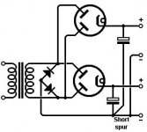
I'm being thick. What is wrong with this configuration? I know it makes more sense just to put the two tubes and reservoirs directly in parallel, but in principle? OK the spur shares return currents from both channels, but this is a valve amp e.g. low current and the wires are presuably short and oversized. What am I missing?Basically, you have a common ground unavoidably at the dirty end of both PSUs,
Attachments
- Status
- Not open for further replies.
- Home
- Amplifiers
- Tubes / Valves
- Tube rectifier and PT without center tap