There is no 'artificial centre tap'...
You can make an artificial cetre tap using a center tapped inductor wired in parallel to the transformer's secondary, and the center tap used and to use this centre tap as ground or return. If the load demand is very low, it can also be done with a couple of resistors.
Last edited:
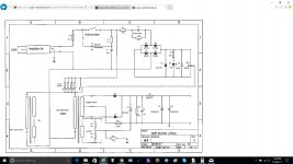
It isn't really two PSUs, which is what he thinks he wants; it is a single PSU with two outputs. However, it is about the best compromise for someone who wants to separate the two channels yet drive them from one secondary (i.e. not separate them!).Merlinb said:What is wrong with this configuration?
There will still be some ripple current to the smoothing caps, which will cause some (hopefully small) ripple voltage in the ground wires. There is also a ground loop (assuming that the source has a common stereo ground) which won't even need AC magnetic flux in it to create hum, as the PSU injects ripple current into it.
I would use a common negative bus in the PSU so it can be grounded at the clean end. This would make it clearer that what we have is one PSU with two output rails which happen to be at about the same voltage.
Aha, got it! 😎It isn't really two PSUs, which is what he thinks he wants; I would use a common negative bus in the PSU so it can be grounded at the clean end
You can make an artificial cetre tap using a center tapped inductor wired in parallel to the transformer's secondary, and the center tap used and to use this centre tap as ground or return. If the load demand is very low, it can also be done with a couple of resistors.
This, as every centre tapped secondary, leads to half the DC voltage, compared to the hybrid bridge's.
Best regards!
This, as every centre tapped secondary, leads to half the DC voltage, compared to the hybrid bridge's.
Best regards!
Of course, but it is other problem.
You can also make a "current doubler", but not with the EZ81 rectifier.
Last edited:
Thanks to Kay Pirinha for answering my question and confirm my thoughs about the second winding resistance --> easy to calculate the resistors to be added to the anodes and simulating in PSUD.
Also thank you all for clarifying what exactly means this type of PS with one secondary winding and 2 tube rectifiers , not a good idea.
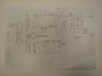
So now I would like to show you the power transformer intended to be used for this amp : is a Raphaelite PW280AB-230.Information about it in link below.
Raphaelite 280W power transformer PW280AB-230 EL34 6L6 KT66 push-pull tube | eBay
Being chinese stuff I dont know if it can handle real 300mA , but I have it laying around waiting for some project to fit in.For me it seems OK handling 150mA as total current, but we will see.
I draw my variant of PS schematic using one 5U4G as rectifier and one B+ rail feeding both channels.I wanted to avoid using a choke,but at 150mA seems to be imposible.
An inrush current limiter will be build on one PCB in front of it --> schematic also attached.
I dont understand exactly what Eli said about how to protect from the inductive kick back so I am not sure if made it right (the 0,01uF / 1kV ceramic cap in series with one 1M resistor bypassing the SS diodes).
Simulating in PSUD this shows that I need only 22 Ohm / 5W as limiter resistors in anodes of 5U4G (not 47 Ohm) --> obtain 305V IF the choke is 75 Ohm.
Looks ok?is something wrong?
PS : using GZ34 and 300V rail from PT I can obtain 317V according PSUD withh the same configuration (22 Ohm / 5W in the anodes).According amp schematic the B+ should be 320V.
Also thank you all for clarifying what exactly means this type of PS with one secondary winding and 2 tube rectifiers , not a good idea.
So now I would like to show you the power transformer intended to be used for this amp : is a Raphaelite PW280AB-230.Information about it in link below.
Raphaelite 280W power transformer PW280AB-230 EL34 6L6 KT66 push-pull tube | eBay
Being chinese stuff I dont know if it can handle real 300mA , but I have it laying around waiting for some project to fit in.For me it seems OK handling 150mA as total current, but we will see.
I draw my variant of PS schematic using one 5U4G as rectifier and one B+ rail feeding both channels.I wanted to avoid using a choke,but at 150mA seems to be imposible.
An inrush current limiter will be build on one PCB in front of it --> schematic also attached.
I dont understand exactly what Eli said about how to protect from the inductive kick back so I am not sure if made it right (the 0,01uF / 1kV ceramic cap in series with one 1M resistor bypassing the SS diodes).
Simulating in PSUD this shows that I need only 22 Ohm / 5W as limiter resistors in anodes of 5U4G (not 47 Ohm) --> obtain 305V IF the choke is 75 Ohm.
Looks ok?is something wrong?
PS : using GZ34 and 300V rail from PT I can obtain 317V according PSUD withh the same configuration (22 Ohm / 5W in the anodes).According amp schematic the B+ should be 320V.
Attachments
Last edited:
- Status
- Not open for further replies.