Basically a Gilbert cell with the top devices implemented by the deflection.As I recall, two 6JH8 tubes have their cathodes connected together over a CCS tail. Then differential X goes between the grid1s. Then deflectors get D1s connected, and separately the D2s connected. Differential Y then goes between D1 and D2 pairs. The product comes out differentially by summing plate currents from cross pairs.
Basically a Gilbert cell with the top devices implemented by the deflection.
Exactly. Could be done with 3 ordinary dual tubes as well, differential pairs. Apparently the deflection part was more accurate, with claims of dist. products 60 dB down. I suppose the scheme could be made even -more- accurate by using a 3rd beam deflector tube in place of the bottom grid1 differential action.
The deflection tubes are however quite finicky, with sensitivity to magnetic fields, and no doubt tube matching. Steel or mu metal shields required. Degaussing of tubes and shields. You won't see them used in any commercial audio product.
Just for fun, would be interesting to make an entire Audio Amp with Beam Deflection tubes. Lots of parallel tubes for the output. They are low gain, low power however, Tube deflector mu around 6 for the 6HW8, probably similar for the others. 3 Watts per plate for the 6JH8. Gain and power could be greatly increased with a cascode above the plates. There even was an obscure beam deflector tube which had a screen grid in the deflector assembly to get high gain.
Last edited:
Thanks; I never knew such a thing even existed!Just for fun, would be interesting to make an entire Audio Amp with Beam Deflection tubes.
I've mentioned them a few times over the years, but usually not much interest. They have low gain (like 2 to 6 gain, unless cascoded) because they act like triodes with the plates acting back on the deflection (unless cascoded). And they are a pain to use with magnetic shielding and degaussing. Should make a good splitter like a Concertina. The other issue is the datasheets don't really give enough information on performance, without really analyzing them thoroughly. At least they are cheap tubes. I've gotten them for less than $2 in the past. The unique thing though is that the deflection mechanism is linear, unlike 3/2 or square law grid1 for conventional tubes. Probably should work up a small circuit board for using them easily, with optional small HV Mosfet cascodes for more gain and biasing/balance controls.
Last edited:

Yup, 7xxx beam deflectors got expensive way back from Ham Radio usage. The best one though, 6JH8 for TV, is so plentiful, you can buy boxes of 100s of them for cheap.
You would think that audio linearity obsessions would have picked up on the Real McCoy linear tubes, but nope, only non-linear grid tubes in audio, and endless discussions on how to get rid of the distortion.
When you load down a grid type triode, the distortion gets worse, so those always have to be lightly loaded to stay near linear. When you load down a deflector type triode, it stays linear. So cascoded deflector types remain linear, unlike the usual cascodes.
Last edited:
How about a cas_cade_ of those, in a fully differential audio design?When you load down a deflector type triode, it stays linear.
Cascade would work, but very little gain per tube (like 2x or 6x), and it will need caps to go from plate V to deflector V for each stage. So practical operation will need cascodes above to get some higher gain in just 1 or 2 stages. The 6ME8 operates with 75V on its deflectors, so maybe some direct connection possible, not as linear as 6JH8 though. 6JH8 operates with 0V on its deflectors. 6ME8 might be good for soft clipping.
Last edited:
Anything that sets you apart from the starved plate 12AX7 crowd, or whatever it is they do to run that tube off just 12V...6ME8 might be good for soft clipping.
Maybe I was just looking for an excuse to melt some more of them.6AQ5s are out!! 7 pins besides.
I realize that you are looking at tubes you have lots of and the 9 pin socket contraption that you have. If I was going to try another massively parallel tube melting experiment, I would need to build the parallel socket contraption, it would need to use sockets that I have a lot of. I have a big box full of nice ceramic chassis mount octals, and a smaller box, but probably equal number of black plastic chassis mount 9 pin sockets that have the bayonet base for a shield.
So I would then look at tubes that I have a bunch of and paid very little for, which would not likely be used in a real project. IE, I have a box full of used pulled 6V6GT's containing 50+ tubes. I'm not going to melt those! In the octal department I have at least 80 25DN6's with plates far bigger than their 15 watt rating that I got in an order from RES when they were on the 100 tubes for $50 list. I have pushed a pair beyond 100 watts without glow, but I would use something bigger if I was to build an amp. I also have a bunch of 6BQ6GA's that melt really good. They cost me about 75 cents each and one of the ugliest pair made over 25 watts per channel in SE for about 10 minutes. The THD slowly climbed by the minute as did the cathode current. I have a good collection of 6W6 types that I would like to try in an UNSET push pull test since their "radio tube derivative, the 50C5 made 20 watts per pair for 12 hours with no degradation, glow, or other issues.
For someone with a 9 pin setup, the 6GC5 and 6DB5 are both 6W6 types in a 9 pin bottle. The 6DB5 is a about the same size as a 6BQ5 / EL84 and has a 10 watt plate rating. The 6GC5 has a fat 9 pin bottle with full size 6W6 guts inside carrying a 12 watt plate rating. I have seen 35 watts flow from a pair of 6W6's but haven't beat on the 6GC5's yet. I only have a few of them, but I have lots of 6DB5's.
From your list the only tubes that I have a good supply of is the 6197 and its sibling the 6CL6. There are probably lots more candidates for "science experiments" that are stashed in my storage trailer next door. I'll go take a look tomorrow.
There has been a 6AR8 rolling around on my desk for several years. Don't know where it came from. It might find its way into a guitar amp experiment soon though. I don't think I have any more BDT's though.
Attachments
Looking in my GE "Essential Characteristics" Handbook for the 6DB5, I see scribbled in "good in triode", but the 1.2 Amp heater power consumption is too high for the crummy 55 mA avg. rating. 6GC5 does a little better at 65 mA avg. 12/6GE5-12/6JN6 do 175 mA on 1.2 Amp heater.
6197 only takes 0.65 Amp for the 6.3V heater and still does 50 mA Avg. I've been impressed by the pentode and triode mode curves for them. 6197 GE MIL contract tubes I have here in abundance from a sealed box, and they seem to be nearly all matched, box of 200. Maybe was an expensive contract! I got them cheap.
A circular aluminum ring could be interesting too.
A Bundt cake ring maybe (Circlotron)?
Bicycle dirt bike wheel rim (wide), suspended above the chassis by spokes from a central pipe. ?
6197 only takes 0.65 Amp for the 6.3V heater and still does 50 mA Avg. I've been impressed by the pentode and triode mode curves for them. 6197 GE MIL contract tubes I have here in abundance from a sealed box, and they seem to be nearly all matched, box of 200. Maybe was an expensive contract! I got them cheap.
I'm inspired to try some paralleling experiments now. Maybe later, they could be put up like Rabbit Ears or a big Triangle (about 22" long) above an amplifier chassis, with the rows of tubes, for a new "look". Would be nice to find some Compactron Rail versions, but not likely from any Electronic Organs. Maybe use some 2" wide Aluminum strips or angles from Lowes or Home Depot. Easy to punch out the holes at least. Maybe I should put some Banana plugs on the end so a whole rack can be plugged into an Amp experiment, like a Big tube. Stock several racks with different tube types.9 pin socket contraption that you have.
A circular aluminum ring could be interesting too.
A Bundt cake ring maybe (Circlotron)?
Bicycle dirt bike wheel rim (wide), suspended above the chassis by spokes from a central pipe. ?
Last edited:
Watcha need is a star engine, sockets in the middle for shortest wireing, tubes pocking out into the air for optimum cooling
How about a Sphere with tubes all over it? Maybe can find some polished metal garden ornament to use.
Some while back I was thinking of putting all the tubes on a sub panel beneath the main chassis. Holes in the chassis to match the tube positions. Then have the sub chassis motorized to ascend slowly up when the unit is powered up. Tubes would be seen rising from the chassis at power on, and descending into the chassis when powered down. Maybe even rocking around across the deck for loud rock music.
Some while back I was thinking of putting all the tubes on a sub panel beneath the main chassis. Holes in the chassis to match the tube positions. Then have the sub chassis motorized to ascend slowly up when the unit is powered up. Tubes would be seen rising from the chassis at power on, and descending into the chassis when powered down. Maybe even rocking around across the deck for loud rock music.
Last edited:
I grew up in south Florida. We had hurricanes nearly every year, usually more than one a year. Most were just a nuisance, but some really screwed things up. After making my own panels to cover all the windows on the house during a storm from 3/4 inch marine plywood that simply slid into heavy aluminum "U channel" that was permanently attached to the house and using them successfully for over 20 years, the lovable insurance company decided that they were not properly approved and explained that they would cancel my coverage if I did not have the proper coverings installed by an approved contractor from their list. Over $4000 later I had the proper panels installed which were simply corrugated galvanized steel sheets held in channels that were far wimpier than what I used. The panels look much like the corrugated roofing panels and sides you see on prefab steel buildings and sheds but about 3 inches deep with a shallower angle to consume less material. After a storm one can find mangled and partially mangled panels everywhere.
Hurricane Wilma trashed south Florida in 2005. The area looked like a war zone with "stuff" everywhere. I picked up several mangled panels and cut off some usable sections. I used a piece of a panel about a foot square for the top side of a chassis made mostly of wood. There was lots of free wood to be found after the storm as well. The panel was mounted such that the zig zag ends fit in routed channels in pine boards that served as the front and rear of the (guitar) amp. I made two amps, one deeper than the other. The electronics and transformers were inside the box and the tubes were mounted on the sloping sides of a corrugated section in a V shaped manner. The first and smaller amp used two 6V6GT's a 5Y3, and three octal 6SN7s or 6SL7s. It was dubbed the "V6." The big boy was the "V8" but I never found eight identically sized tubes that sounded right in it.
The 6197 is a 6CL6 with a cathode built for possible long term operation without current flow. This is mandatory for computer use where the tube is either non conducting or saturated for its entire life. I know that I had a LARGE quantity of these from a lot of over 100,000 old tubes that I got about 30 years ago. All were pulled from "military spares" and presumed to be good. The 6AQ5's that were intact with usable pins were indeed mostly good. They had been in an abandoned warehouse in central Florida for an unknown length of time before they were found when the old wooden warehouses were being demolished for a housing project. Vandals had trashed most of the large tubes and all of the windows in the building, and even the vagrants had left, leaving lots of broken glass (tubes and bottles) and bird crap everywhere.
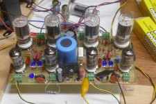
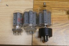
One day while wandering through the ESRC warehouse I discovered a tiny sweep tube called the 6GF5. It looks like a 6GE5 with its plate wings clipped, stuffed into a skinny bottle. The 6GE5 is simply a 6DQ6B in a compactron bottle without a plate cap. Stan had never sold any, so I got a BIG box full cheap. I eventually found a data sheet that leads me to believe that it is a shrunken 6GE5. I have seen 80 watts from a pair at under 3% THD without any glow. The picture shows a 6GF5 on the left, a 6GE5 and a 6DQ6B. the board uses 6GF5's in UNSET push pull.
Hurricane Wilma trashed south Florida in 2005. The area looked like a war zone with "stuff" everywhere. I picked up several mangled panels and cut off some usable sections. I used a piece of a panel about a foot square for the top side of a chassis made mostly of wood. There was lots of free wood to be found after the storm as well. The panel was mounted such that the zig zag ends fit in routed channels in pine boards that served as the front and rear of the (guitar) amp. I made two amps, one deeper than the other. The electronics and transformers were inside the box and the tubes were mounted on the sloping sides of a corrugated section in a V shaped manner. The first and smaller amp used two 6V6GT's a 5Y3, and three octal 6SN7s or 6SL7s. It was dubbed the "V6." The big boy was the "V8" but I never found eight identically sized tubes that sounded right in it.
Somewhere in my brain was an image of a radial aircraft engine styled tube amp with 6 or 8 tubes. I remember seeing it pictured somewhere, and since it provided the inspiration for my "V" engine styled amps, it had to be before 2005. Google can't find it.Watcha need is a star engine, sockets in the middle for shortest wireing, tubes pocking out into the air for optimum cooling
The 6DB5 and 6GC5 are derivatives of the 6W6 as is the 50L6 and its other heater voltage siblings. The 7.5 watt heater IS hungry, but it puts out a big fat space charge cloud which leads to better overall efficiency when you are trying to reduce the plate dissipation as the tube is operating at or near its saturation region. This is why it's easier to squeeze more power from a 18 watt sweep tube than a 30 watt 6L6GC. Some of that excess heater power can be recovered in the plate circuit.Looking in my GE "Essential Characteristics" Handbook for the 6DB5, I see scribbled in "good in triode", but the 1.2 Amp heater power consumption is too high for the crummy 55 mA avg. rating. 6GC5 does a little better at 65 mA avg. 12/6GE5-12/6JN6 do 175 mA on 1.2 Amp heater.
6197 only takes 0.65 Amp for the 6.3V heater and still does 50 mA Avg. I've been impressed by the pentode and triode mode curves for them. 6197 GE MIL contract tubes I have here in abundance from a sealed box, and they seem to be nearly all matched, box of 200. Maybe was an expensive contract! I got them cheap.
The 6197 is a 6CL6 with a cathode built for possible long term operation without current flow. This is mandatory for computer use where the tube is either non conducting or saturated for its entire life. I know that I had a LARGE quantity of these from a lot of over 100,000 old tubes that I got about 30 years ago. All were pulled from "military spares" and presumed to be good. The 6AQ5's that were intact with usable pins were indeed mostly good. They had been in an abandoned warehouse in central Florida for an unknown length of time before they were found when the old wooden warehouses were being demolished for a housing project. Vandals had trashed most of the large tubes and all of the windows in the building, and even the vagrants had left, leaving lots of broken glass (tubes and bottles) and bird crap everywhere.
One day while wandering through the ESRC warehouse I discovered a tiny sweep tube called the 6GF5. It looks like a 6GE5 with its plate wings clipped, stuffed into a skinny bottle. The 6GE5 is simply a 6DQ6B in a compactron bottle without a plate cap. Stan had never sold any, so I got a BIG box full cheap. I eventually found a data sheet that leads me to believe that it is a shrunken 6GE5. I have seen 80 watts from a pair at under 3% THD without any glow. The picture shows a 6GF5 on the left, a 6GE5 and a 6DQ6B. the board uses 6GF5's in UNSET push pull.
Attachments

I seem to recall one 6GF5 "shaking in it's boots" next to some of the "big bad boys" on the bench some while back. (35LR6, 6HJ5, 26LW6, ....) The 6GF5s have done well. They curve trace very much like the 6GE5 and 6DQ6B.
I tried some 6GC5 tubes next to each other on the 9 pin "tube rails" here ( 1-5/16" spacing ) and they almost touch each other. Like 3/16" gap. 6GF5 is the same 1-1/8" diameter, but a Compactron base. The regular 9 pin tubes have 1/2" spacing ( 13/16" diam. tubes ). If I make some similar ( from 22" long 2" wide Aluminum angle ) rails for 1.5" diam. Compactrons, there will be room for only 10 tubes. But then a 240 Watt 6HJ5 rail would be impressive still. Maybe two groups of 5x 6HJ5 for P-P. (Well, I've only got 100 Watt Edcor and Hammond OTs. Maybe I need to split those further for stereo.) Don't think I'll try to tackle plate cap type tube rails.
I recall seeing an OTL Amp with box-like rails above the tube rows for all the plate caps. And whoever bought all those 13GB5 tubes are probably dealing with them too.
Which reminds me that I should look for some U or double L strips to cover the tube socket wiring for the rails.
I don't think I'll ever be trying OTL designs with lots of tubes. Only thing close will be 2x 6528 tubes for trying out the OTL cheat patent # US4614914 with an 80 Watt 1200 Ohm P-P Toroid OT ( Toroidy ) versus OTL configured. ( like only 8 Watts OTL )
Last edited:
I seem to recall one 6GF5 "shaking in it's boots" next to some of the "big bad boys" on the bench some while back.
I wonder who said that 14 years ago?
Posts #243 and 244 here:
https://www.diyaudio.com/community/threads/posted-new-p-p-power-amp-design.151206/page-13
That's good to know since I have seen documentation allegedly from GE stating that they were 6BQ6GT's and they were 6DQ6B's. They can't be both. That board was actually the first time that I got the UNSET concept to work right after many years of tinkering with it. I wandered over to my storage trailer today and found that I have over 200 of the 6GF5's.The 6GF5s have done well. They curve trace very much like the 6GE5 and 6DQ6B.
And whoever bought all those 13GB5 tubes are probably dealing with them too.
I got a fer 13GB5's when they were on the dollar menu and worked up a 100 WPC board to use them in, but when I went back to Stan's place to get more, he said that someone bought them all. That ended the "Not Quite So Simple PP" idea.
The 6CU6, 6BQ6GA, 6AV5GA all have about the same size plate as 6GE5/6JN6/6DQ6B but the cathode current rating increased quite a bit for the latter ones and also the 6GF5. That boosted the gm some too, using higher current.
38HE7 is another interesting one, with something close to the 21HB5A pentode inside, in similar trimmed plate form like the 6GF5. It can usually be run alone (without the damper diode) by using 21V on pins 10 and 12. Probably good for 15 Watts diss. without the damper diode powered. Same 230mA DC rating as the 21HB5A.
------------------------
A year or two ago there was a thread here about -LOW- N Fdbk causing higher harmonics, by re-circulation of the error correction signal thru the distorting amplifier repeatedly. A published paper showed the higher harmonics for a special test amp versus loop gain. I don't doubt the results, but I don't believe there is actually any problem. No one has ever complained about the sound of low N Fdbk, quite the contrary actually, other than the native amplifier distortion not being totally cleaned up.
The perceived problem comes from the usual discrete FFT (integer harmonics) giving misleading spectra. The discrete FFT cannot represent non-integer harmonics, and those then get represented by a series of alternating polarity higher harmonics that trail off, which look bad, but aren't really,
Anyway this started me thinking of some scheme to avoid Fdbk re-circulation, just for the fun of it. And, lo-and-behold, I found a scheme that not only works, but does not even require the usual excess gain in the amplifier. Only enough gain to counter the OT V reduction along with just enough gain to power the load as desired. I mention this because the Beam Deflection tubes are a natural fit, although not a necessity. The scheme re-writes the book on N FDBK.
Here is how it works. Take a typical distorting amplifier of gain A, and put a gain modifier (6JH8 say) at the input, and another gain modifier after the output, but with an attenuator in-between to reduce the amplified signal back to the input level ( atten. = 1/gain A). So the gain modifiers are working with similar signal levels. The two gain modifiers operate in complementary fashion, x(1+e) and x(1-e) so as to cancel each other out. "e" is the nominal error detected in the amplifier gain from instantaneous distortion, so a very small modification to gain. The load still connects directly to the direct amplifier output. The 1st gain modifier is used to remove distortion from the amplifier channel by full bandwidth control of gain to make it constant.
The output of the last gain modifier (forming a 'do-nothing" Fdbk channel) restores the original un-modified signal, which is then compared to the actual input signal to derive the gain error "e" and control the gain modifiers. The 1st modifier removing the distortion, the second modifier returning the signal to the un-modified level, other than the amplifier distortion now in it. Since the Amp error does not ever diminish after the last modifier, we do not need extreme gain to still see it for operation after correction. Essentially, the complementary gain modifiers give us a "do nothing" N Fdbk channel, so the amplifier error is always present there, un-diminished, for controlling the error correction. Should this maybe be called "Do Nothing" FDBK? Or, do no harm.....
There is an issue that still has to be dealt with, since the detected error reverses sign with signal polarity. This is readily fixable by putting a +1 offset in the error detected output, along with a polarity reversed error with the same +1 offset. A Schottky or Germaniom diode bridge(s) selects the most positive one for forming the 1+e and 1-e control signals (the +1 keeps them away from the initial diode curvature region and forms the control signals as needed). Obviously the amplifier phase should stay near constant for this to work well, but the lowish gain required should help with that. Bandwidth in the loop needs to be above the signal. This has not been tested yet! On the to-do list.
Last edited:
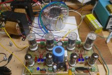
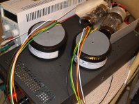
I got my Toroidy 1200 Ohm P-P 80 Watt OTs in. TTG-6C33CPP Now I can do experiments with 6+6 10 Watt tubes on the "tube rails" or the OTL cheat patent experiment using 6528 big 60 Watt regulator tubes. (and try some TV Sweep tubes too.) Either 80 Watt with the OT or 8 Watt in OTL configuration. US patent (Audio Precision) US4614914, allows removing the xfmr artifacts (magnetizing current and primary resistance ) so that the OT will be completely transparent.

Attachments
Last edited:
The equipment you guys have reminds me of the lab we had at work. I recognize the thing those transformers are sitting on, without a clear shot of its front panel. (I couldnt say what voltage / current model it is, though)
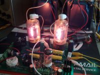
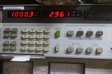
That's the Xantrex XHR 0-7.5 V 130 Amp Bench supply I dragged up from the basement to try and light up a 7241 tube (on top there with a 6528 tube also).
The 7241 had air in it. I have to return it for a refund. (it was only $50, I should have guessed ) Otherwise I would crank the V up and turn it into an arc lamp. (Tubelab style) I'll be staying with 6528 or 6336 for big tubes, SO much cheaper and new.
During the DOT COM crash, years back, I stocked up on various Xantrex bench supplies. I could get the XHR 1000W models (not working) for $50 to $75 and then fix them. Got 600V, 300V. and 150V. 100V models for tubes (or SS). Xantrex XT250V models for screen grid supplies, HPD60 supplies for heaters. XT120 models for biasing. The prices on Ebay now are just shocking.
Last edited:
- Home
- Amplifiers
- Tubes / Valves
- Tube Rails for paralleling tubes