Hi Guys
Post-36 describes how to make the DC standoff. TUT3 (The Ultimate Tone vol.3) illustrates this in all of its projects and also shows how to wire any circuit for lowest noise and best note articulation. DC standoffs are always a good idea and no DC flows through the winding - how could it?
Even were you to bridge rectify the 12Vac to use for heaters or for auxiliaries like channel switching, there is no DC through the windings. However, this aux supply would be floating if it were referenced to a DC standoff - not a problem if the switching is local and there is no need to connect to something ground-referenced.
In the simplest scenario of having just the 12V windings tied to each other, they should still be tied to ground in some way rather than be left floating. The ground tie can be resistive or capacitive, although the former is preferred. The DC standoff is a ground tie as the filtered reference point is AC ground, just as all supply nodes filtered by a capacitor are.
The TUT-series is less expensive than a college education!
Have fun
🙂The TUT-series is less expensive than a college education!
That accurately defines the price range for the TUT books!
(I have 'a few' of the TUT books, but the range seems to expand with time. $$)
The TUT-series is less expensive than a college education!
I couldn't afford that either at the time. Somehow I worked my way up from assembly line tech to engineer without one, then Motorola paid for me to go to college....twice. Total costs, over $50K, glad I didn't pay for that.
Any learning material is worth what you get out of it. Books, videos, even classroom time is worth the price IF you learn enough to enable you to do something that you couldn't before, or in the corporate world I lived in for 41 years, make more money for yourself, the company, or both, than the cost of the educational experience.
Did I earn more in the 15 years that I worked after collecting my last degree than I paid for it? Absolutely, since it only cost me about $2500 for gas, books, and a $300 calculator I never used after college.
Did Motorola recover their $50K? I don't know, that's for the spreadsheet pushers to decide. The same guys that decided that the older employees were too expensive to keep, and paid me a lot of money to "retire."
I have never been a good reader, and books are not the most efficient way for me to learn something. I would rather spend the money on a box full of parts, and learn by trying something. Most guitar amps are a hand full of 12AX7's connected to a set of the usual output tubes. I have been building them for 50 years, so I would probably not get a lot of new knowledge from your books, or anybody else's either, so the nearly $400 would not be well spent for someone on a limited budget.
That's not to say that they wouldn't be a good value for someone starting down the road of DIY guitar amp building, amp repairs, or amp mods. In fact I have heard that TUT is excellent in that regard.
I picked up a number of 12V transformers and tried the back to back thing. Never really worked as well as I liked. Always losses and with 120V in you do not get the 120V out. Rather get a 120:120/120:240V transformer for the high voltage duties and get a switching wallwart to supply 12vdc.
tried the back to back thing. Never really worked as well as I liked.
It works, but not great. 120:12 volt transformer to 12:240 volt transformer (same Hammond 186E12 transformer) results in about 310 volts with a 70 mA idle current (2 X 6V6GT, 1X 12SL7, 1X 12SK7). Voltage sags to 280 when driven to continuous clipping. Amp makes about 12 watts at the edge of clipping. Two Hammond transformers at $18.26 each.
Same 12 volt transformer feeding the heaters. Triad N68X 50 VA isolation transformer feeding a voltage doubler for the plate supply. B+ is now 330 volts with a 75 mA idle current, and sags to 310 when cranked hard. Amp makes 15 watts and requires one $18.26 Hammond transformer and one $16.26 Triad transformer. Save $2 gain 3 watts.......
Same amp. One 12 volt 6 amp "Kastar replacement AC adapter" intended for computer display from Amazon $7.99, one 12 volt to 110 volt 75 watt power inverter from Amazon $12.99.
Inverter dissected and AC chopper removed, transformer secondary rectifiers reconfigured as a voltage doubler (tedious work on tiny parts). I'm working on a better boost converter.
B+ is 320 volts at idle, 310 cranked. Amp makes about 14 watts. This option cost the least, depending on the magnetics in the boost converter. This works anywhere (100 to 240V 50/60 Hz) without swapping transformer wiring and GETS THE AC LINE COMPLETELY OUT OF THE AMP!
@ Printer2: My experience (so far) with back to back trafos is similar. Also the resulting PSU has quite a high impedance with voltage dropping as current draw increases - built in voltage sag 🙂
If I want real world 240v B+ out I back to back a 12vac plug pack into a larger VA 240v:9v trafo (yeah, let me hear the screams about trafo saturation but I have had no such trouble with my sub 6w amps - other than cries of "turn down that racket!" 🙁 ).
(Sorry Tubelab - I was typing while you were posting. I've persevered with this type of PSU to "get the AC line completely out of the amp" while teaching DIY to teenagers)
Last edited:
It works, but not great. 120:12 volt transformer to 12:240 volt transformer (same Hammond 186E12 transformer) results in about 310 volts with a 70 mA idle current (2 X 6V6GT, 1X 12SL7, 1X 12SK7). Voltage sags to 280 when driven to continuous clipping. Amp makes about 12 watts at the edge of clipping. Two Hammond transformers at $18.26 each.
Same 12 volt transformer feeding the heaters. Triad N68X 50 VA isolation transformer feeding a voltage doubler for the plate supply. B+ is now 330 volts with a 75 mA idle current, and sags to 310 when cranked hard. Amp makes 15 watts and requires one $18.26 Hammond transformer and one $16.26 Triad transformer. Save $2 gain 3 watts.......
Same amp. One 12 volt 6 amp "Kastar replacement AC adapter" intended for computer display from Amazon $7.99, one 12 volt to 110 volt 75 watt power inverter from Amazon $12.99.
Inverter dissected and AC chopper removed, transformer secondary rectifiers reconfigured as a voltage doubler (tedious work on tiny parts). I'm working on a better boost converter.
B+ is 320 volts at idle, 310 cranked. Amp makes about 14 watts. This option cost the least, depending on the magnetics in the boost converter. This works anywhere (100 to 240V 50/60 Hz) without swapping transformer wiring and GETS THE AC LINE COMPLETELY OUT OF THE AMP!
I picked up some laptop bricks and wanted to step step up the voltage rather than down. Who knows if I will ever get around to it?
Hi Guys
The back-to-back PTs works fine if you know what you are doing. As I said above, those potted toroids have a high temp rise at rated output with a correspondingly high EMI output. If you use semi-toroids like Hammond's 229-series, you have to keep the loading on the windings balanced to maintain acceptable noise.
All of these small PTs have poor voltage regulation to begin with, so their losses are expected to be high. But who cares? If you use them in a sensible fashion, you get voltages that are "real tube" levels and can do all kinds of things without having to buy a "proper" PT. The proper PT may not fit into 1U where most of these others will.
As the Dumpster chapter of TUT5 shows, you can put the outputs of two or more of these PTs in series if you need very high voltage. Most of these small toroids and semi-toroids have a 4kV isolation rating. You have to be more careful with small EI types as these may only have a 1kV insulation rating, or even less.
Have fun
Used the Hammond 228D12 to make a low wattage 5E3.
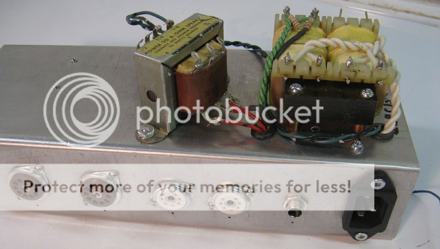
Used one primary for the primary (Duh) and used the second one for a secondary that I used with a doubler. One secondary to feed the heaters. Made for a nice little 5W amp.

Used one primary for the primary (Duh) and used the second one for a secondary that I used with a doubler. One secondary to feed the heaters. Made for a nice little 5W amp.
Hi Guys
Dual primaries are supposed to be used together ALL the time as primaries. To do otherwise risks damage to the PT. Each primary is only rated for half of the total input power.
You can be forgiven for making such an error, when there are people who should know better providing examples of such use. One was Eric Barbour and a little pedal box with a tube or two in it. He used a 229 just as you did, with one primary used for the plate supply and the secondaries used for the filament. This is "clever" in the worst possible connotation of the word.
It is also no wonder if one uses a PT in this fashion and finds the result to be unsatisfying. You can accept certain limitations if you use a device rated far above the intended load.
Have fun
To do otherwise risks damage to the PT
It is one thing to miswire a power transformer when the transformer could be damaged. To understand and accept the risk of poor performance, and possibly a toasted transformer is acceptable only if you know and understand ALL the risks, and accept them.
These Hammonds APPEAR to have the individual primaries wound separately with air and plastic separating them. I have not verified this particular Hammond model but this is the case on some similar looking Hammonds that I have in a 10 year old project. What I'm about to say does NOT apply if this IS the case.
I saw this practice discussed here a lot several years ago in regard to a line of plastic cased toroidal transformers (Talema?) and a couple of preamp or line stage designs. The transformers in question had bifilar primary windings. The ONLY thing separating the two primary windings is a layer of thin enamel put on the wire by the vendor, who is likely in China. If this insulation fails you risk putting line voltage on your guitar! If the person doing this does not understand the situation and does overload the half primary, the risk becomes very real.
Hi Guys
Dual primaries are supposed to be used together ALL the time as primaries. To do otherwise risks damage to the PT. Each primary is only rated for half of the total input power.
You can be forgiven for making such an error, when there are people who should know better providing examples of such use. One was Eric Barbour and a little pedal box with a tube or two in it. He used a 229 just as you did, with one primary used for the plate supply and the secondaries used for the filament. This is "clever" in the worst possible connotation of the word.
It is also no wonder if one uses a PT in this fashion and finds the result to be unsatisfying. You can accept certain limitations if you use a device rated far above the intended load.
Have fun
No error made. The transformer was delivering a little more than half the VA it was rated for, and as you know (Being another Canadian), Hammond does overbuild their transformers. Picked it to fit in a another enclosure but delayed building that amp so used the transformer. No adverse effects found, working good to this day.
Think doing the back to back transformer thing is no more questionable practice than using one primary winding for a secondary. The unsatisfied results I found was with the back to back transformer method not the use of the Hammond I showed. It must be said that the transformer must be overrated and the primaries separated electrically and mechanically. Heater draw - 6W, so with the transformer rated for 24 VA that leaves 18 VA for a 3W (clean) amp. Hardly smoking the primary winding.
Hi Guys
" The ONLY thing separating the two primary windings is a layer of thin enamel put on the wire by the vendor, who is likely in China. If this insulation fails you risk putting line voltage on your guitar! If the person doing this does not understand the situation and does overload the half primary, the risk becomes very real."
Half that statement is completely false.
You are correct that in a bifilar winding the two coils are only separated by the two layers of enamel on the wires. This provides a minimum isolation of 500V which is more than ample given the voltages across the windings when used as a pair. Most high-temp transformer wire has greater insulation than this and is pretty much standard.
Putting line voltage on your guitar? Assuming you mean that one primary is used as the plate winding and one for mains, are you also assuming that the safety ground is defeated? and that improper fusing is also the case? The latter is actually a valid assumption for most DIY builds and for nearly all vintage builds and yes, even for many current production amps.
China? Most of those little blue toroids are from India - which I suppose you also have an issue with? The quality of these devices is almost entirely dictated by the moneyed interests who commission them, and most of these parties are in the USA and some from Europe. Amveco is Italian. Amgis is US. Talema is Irish. Personally I have never had a problem using those PTs. High end audio companies use them too, such as Soulution in Switzerland.
"Heater draw - 6W, so with the transformer rated for 24 VA that leaves 18 VA for a 3W (clean) amp. Hardly smoking the primary winding."
The math is wonky since you say you used one primary for the plate. This effectively makes the PT a 12VA unit. 6W for heaters leaves 6W for plate not 18W. That allows about 2Wrms of audio if you're lucky. The actual power output might measure higher but if you run the thing flat out all the time the risk of failure is higher than were the device used as intended.
Hammond is free with information about their transformers. They will tell you if your intended use will damage their part, or if it will be fine. Where in the past their designs were a bit over-built, that cannot be assumed for current production since competition drives prices down and thus costs have to be carefully honed. Take for example the OTs for tube amps: The weights listed up until the 5C-00 catalog stated 1650NB weighs 8-lbs. An actual 1650N from the day weighs 6.4-lbs.
I am always one for pushing the envelope and finding alternate ways to do things. However, I find there are some conventions that really do make sense.
Have fun
Putting line voltage on your guitar? Assuming you mean that one primary is used as the plate winding and one for mains, are you also assuming that the safety ground is defeated?
YES!!!! I MUST assume that this is the case when I post a schematic and someone that I don't know, and have no knowledge of his skill level builds it. To do otherwise is foolish. For this reason, I will never post a schematic that uses a transformer in this manner, and I will continue to warn others of this possibility whenever I see it.
There have been schematics posted on this forum and others, where using one primary as a secondary. I have expressed these same concerns then, as I do now, because it imposed an additional level of risk upon the used that he may not know about, or understand. Yes, this requires two "failures" to fry someone, but they are both real possibilities.
Even if someone builds a guitar amp exactly according to a published set of plans, and those plans are technically correct, and safe, will the builder always have it properly grounded during use? I have two of these, and I'm sure there are more out there. Can you say that every stage setup, especially temporary outdoor setups, are wired correctly?
that improper fusing is also the case?
If a power transformer develops a short between the primary, and a secondary, or its housing, AND the amp is not grounded (for whatever reason) the fuse will not blow, and you could have line voltage on your guitar! The manner in which most players hold the neck makes it rather hard to let go of the neck if an electrical shock should occur.
China? Most of those little blue toroids are from India - which I suppose you also have an issue with?
I am not being specific to one brand of little blue toroid, and regardless of where it is made, where was the wire made? The Triads that I have been using are Chinese.
The quality of these devices is almost entirely dictated by the moneyed interests who commission them, and most of these parties are in the USA
I spent several years of my career designing cell phones, and working with the manufacturing people solving problems. I only have knowledge of the factory process in Malaysia. and China. We shut down our factory and built in both places. I can state that in both countries the prime directive is cost, above all other things, including specs, process, and quality. The Malaysian factory which was company owned, would eventually get it right, but you had to have put your factory people there for 6 months to a year. The Chinese phones were all built in the Foxconn facility, as were Apple, and Nokia phones. Even with every process in the entire build documented, things would get messed up, often intentionally. Quality was directly dependent on the run rate.
Personally I have never had a problem using those PTs.
I have not either, but I am not willing to trust my safety to some unknown wire insulation in a transformer put together in an unknown factory, wherever it may be. We have agreed that this type of connection isn't correct. I'm not trying to step on anybody's toes, but I will continue to state my opinion on electrical safety whenever I see a risk being taken that the user may not be aware of.
BTW, I have seen ONE power transformer with a primary to case short, and ONE OPT with a primary to secondary short. Both were vintage transformers, and both were exposed to the south Florida humidity for an extended time, but it does happen.
Attachments
Hi Guys
"BTW, I have seen ONE power transformer with a primary to case short, and ONE OPT with a primary to secondary short. Both were vintage transformers"
The joys of paper insulation! ... which is why it is illegal in most countries.
It's next to impossible to have a short to core in a toroid as the core is wrapped in plastic tape before any wire is wound. Besides, the core is electrically floating so even if a short happened there would be no path to the circuit or the chassis.
All of the improper use of primaries aside, my main point was to say that back-to-back PTs works fine and is safe as far as the transformers go.
Every assembly is only as safe as the design permits and as the operator cares to be.
Have fun
"Heater draw - 6W, so with the transformer rated for 24 VA that leaves 18 VA for a 3W (clean) amp. Hardly smoking the primary winding."
The math is wonky since you say you used one primary for the plate. This effectively makes the PT a 12VA unit. 6W for heaters leaves 6W for plate not 18W. That allows about 2Wrms of audio if you're lucky. The actual power output might measure higher but if you run the thing flat out all the time the risk of failure is higher than were the device used as intended.
Hammond is free with information about their transformers. They will tell you if your intended use will damage their part, or if it will be fine. Where in the past their designs were a bit over-built, that cannot be assumed for current production since competition drives prices down and thus costs have to be carefully honed. Take for example the OTs for tube amps: The weights listed up until the 5C-00 catalog stated 1650NB weighs 8-lbs. An actual 1650N from the day weighs 6.4-lbs.
I am always one for pushing the envelope and finding alternate ways to do things. However, I find there are some conventions that really do make sense.
Have fun
You are right, did a quick answer this morning and did not think the VA's through. So 6W for the plates. Say 3W power out and throw away the other 3W. Still sounds fine. Now, this is assuming using one winding will only supply 12 VA. Since the windings barely rise in temperature and I am nowhere close to saturating the core I do not see what the issue is. Hardly pushing the envelope here.
Hi Guys
The issue is that each primary is only designed to support half the load of the transformer. The wire is guaged accordingly, so using the PT up to half the total rating does not cause a problem with just one primary for mains input.
If you try to pull more than half-power this way, the single primary will heat up a lot more than it otherwise would since its DCR is fixed. This is made worse by a hot environment and/or a poorly regulated mains that tends to be higher than nominal.
Just a note: In your power calculation, you can't assume a power output ahead of knowing the available plate power. You go from the latter and end with the former. You can also measure the output power and see what the reality is - maybe you aimed at 3W and are getting it. Design procedures for SE are available in TUTs and places on the web.
Have fun
But that is my point. I ran the amp on one primary winding on full power for a while and felt the transformer with my hand. Not hot at all so I took it as not a problem. May not be an engineered solution but let's face it, it is only 12W. And a fraction of that is being dissipated by the transformer. And with the surface area of the transformer the few watts it is giving off won't be much of a temperature rise.
I know what you are getting at but in this cases everything is fine. If it puts your mind at ease I have 12 years of CET behind my name and two electrical licences. Play with a lot more serious power than a little guitar amp. Actually I have stayed away from all but basic tube theory (I will do a load line) just because I don't want it to seem like work. Still some wonder when I put something together. As you like to advise, I'm just doing it for fun.
I know what you are getting at but in this cases everything is fine. If it puts your mind at ease I have 12 years of CET behind my name and two electrical licences. Play with a lot more serious power than a little guitar amp. Actually I have stayed away from all but basic tube theory (I will do a load line) just because I don't want it to seem like work. Still some wonder when I put something together. As you like to advise, I'm just doing it for fun.
Guys,
I forgot to bring this up earlier. Everybody that builds amps, computers, or other gizmos that plug into the wall outlet needs one of these.
http://www.amazon.com/P3-P4400-Elec...UTF8&qid=1453778184&sr=1-1&keywords=killawatt
It will tell you just how many watts, or VA (important to a transformer) your device draws from the wall outlet. Amazon or Newegg puts them on sale every so often. I think I paid $19.95 for mine.
Using a power transformer this way while it definitely works is a somewhat risky proposition. The problem is you don't know what if any additional insulation exists between those two primaries, worst case you are depending on the varnish insulation on the magnet wire to keep you safe. Insulation failures may not be frequent, but their incidence is not zero either, and if it happens you could end up with AC mains on your chassis and worse an electrocution hazard exists if the chassis is not safety grounded for any reason. (Bad outlet, etc.) The probability is low, but not zero..
Some thing else to consider is how much power that single winding can handle on its own, properly speaking the transformer should be derated to roughly 50% of its VA rating to avoid overheating and potentially burning the insulation. (Based on double the effective winding resistance). Holding it in your hand is not going to tell you much about how hot that winding is now getting. You can use the rise of resistance method to make an approximate determination.
Some thing else to consider is how much power that single winding can handle on its own, properly speaking the transformer should be derated to roughly 50% of its VA rating to avoid overheating and potentially burning the insulation. (Based on double the effective winding resistance). Holding it in your hand is not going to tell you much about how hot that winding is now getting. You can use the rise of resistance method to make an approximate determination.
- Status
- Not open for further replies.
- Home
- Live Sound
- Instruments and Amps
- Tube preamp Design for Guitar