Using a power transformer this way while it definitely works is a somewhat risky proposition. The problem is you don't know what if any additional insulation exists between those two primaries, worst case you are depending on the varnish insulation on the magnet wire to keep you safe. Insulation failures may not be frequent, but their incidence is not zero either, and if it happens you could end up with AC mains on your chassis and worse an electrocution hazard exists if the chassis is not safety grounded for any reason. (Bad outlet, etc.) The probability is low, but not zero..
Some thing else to consider is how much power that single winding can handle on its own, properly speaking the transformer should be derated to roughly 50% of its VA rating to avoid overheating and potentially burning the insulation. (Based on double the effective winding resistance). Holding it in your hand is not going to tell you much about how hot that winding is now getting. You can use the rise of resistance method to make an approximate determination.
Not your regular transformer. A square toroidal transformer.
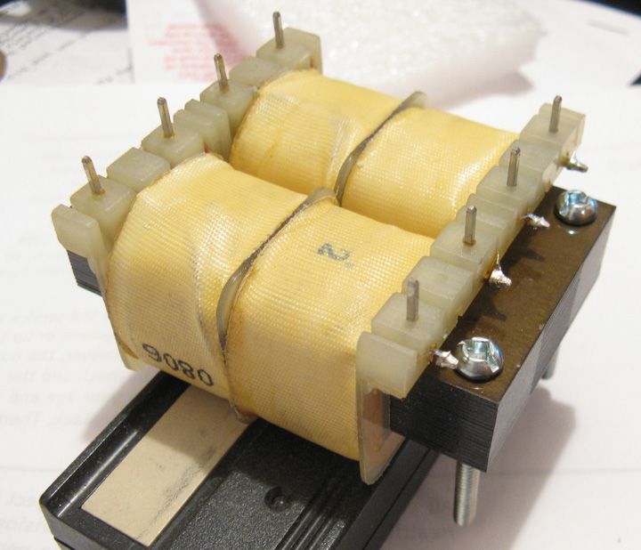
Four coils separately wound, each isolated from each other by the plastic bobbin. Transformer is being used at half its VA rating. No appreciable heat rise with amp driven to clipping for an extended period of time. Would not recommend doing the same thing with a regular transformer but this design is about as safe (voltage related) as you can get. Again, don't use it at full rated VA. I hope it is more clear now.
Last edited:
This is a split bobbin flat pack transformer and yes this will be absolutely safe as employed as long as you live within the decreased VA rating. Glad we finally got to the bottom of this, should be just fine.
i'm somewhat ready building, and i'm getting 18 vac for my heaters, without the tubes in.
I was aiming for 12~, wil putting the 2 tubes in drop it to 12~?, if not is it harmful to run it temporary at a higher voltage somewhere between 12-18 ?
I was aiming for 12~, wil putting the 2 tubes in drop it to 12~?, if not is it harmful to run it temporary at a higher voltage somewhere between 12-18 ?
Hi Guys
As I mentioned previously, the regulation of these small-VA PTs is very poor. The rated output voltage is at full load current and the specified input voltage. Depending on the VA, it is not unusual to see the unloaded voltages you have Saus.
You can easily do a test load of two tube heaters and see where the voltage lands. The tubes are okay at +/-10% of the voltage rating (12.6V). If you are concerned about damaging the tube heaters in this test, you can use some power resistors. Each tube heater when hot looks like 12V/150mA=80R and dissipates about 2W. So, any way you can podge together an 80R load or 40R as two tubes sim will be fine. The latter could be four 10R-3W+ in series.
In the units I build using back-to-back PTs, I have a voltage regulator for the heaters as it also supports auxiliary circuits for switching, etc.The LED is wired across the raw 12Vac with appropriate current-limiting resistance and a reverse protection diode and noise cap. This way, the power LED goes on/off with the mains switch.
kevinkr: Those "flat" PTs are called semi-torids. They are always wound with a primary and a secondary on each long leg of the core, which is partly how they get 4kV isolation easily and also why the loading on each winding pair must be equal.
Have fun
kevinkr: Those "flat" PTs are called semi-torids. They are always wound with a primary and a secondary on each long leg of the core, which is partly how they get 4kV isolation easily and also why the loading on each winding pair must be equal.
Have fun
The loading have to be equal? The core only knows flux is put in and taken out. If there was only two coils on the core the core would not care if one was on each leg or both were on one leg. The magnetic flux has to go around the complete magnetic circuit whether the secondary was beside the primary or not. The core does not care if the 'secondary' was putting out 6 VAC or 120 VAC. It only cares that it does not get saturated.
Take a regular toroid core and wind a loop through it as the primary. Wind a second loop through it as the secondary. You can place the secondary loop to the left of the primary coil, move it around the coil at any position around the coil, even to the right of the primary coil. You will get the same magnetic lines of flux developed by the primary and the same current through the secondary no matter where the coils are situated.
It has been 15 years since I had to concern myself with magnetic circuits, from what I remember this is how I understand it.
Hi Guys
As stated in an earlier post, the loading has to be equal on the windings of a semi-toroid if you want minimum EMI.
This is a concern not to be taken lightly when building a tube circuit, especially since the tendency in the use of such PTs is to make the whole unit as compact as possible. It is generally a mistake to try to make the layout of a tube circuit too small.
Have fun
Same amp. One 12 volt 6 amp "Kastar replacement AC adapter" intended for computer display from Amazon $7.99, one 12 volt to 110 volt 75 watt power inverter from Amazon $12.99.
Inverter dissected and AC chopper removed, transformer secondary rectifiers reconfigured as a voltage doubler (tedious work on tiny parts). I'm working on a better boost converter.
B+ is 320 volts at idle, 310 cranked. Amp makes about 14 watts. This option cost the least, depending on the magnetics in the boost converter. This works anywhere (100 to 240V 50/60 Hz) without swapping transformer wiring and GETS THE AC LINE COMPLETELY OUT OF THE AMP!
Seeing how transformer costs are rising and how our currency here in Canada is dwindling in purchasing power, this is the kind of cool idea to implement.
Any chance of a step-by-step tutorial, George?
Seeing how transformer costs are rising and how our currency here in Canada is dwindling in purchasing power, this is the kind of cool idea to implement.
Any chance of a step-by-step tutorial, George?
I would not trust the 6A rating unless it had a name like HP or Sanyo on it. Bought some no name supplies as they were the right price, the problem is that some do not deliver on the full current unless supplied by 200V or above. What I do is go to a thrift store and pick up a brick ($2) from a laptop or printer for the heaters. Then I use a Hammond 186D120 (120:120-120, 30VA). At Tip Top Electronics it is $18.59 CND.
I have used it for 160V supplies to 390V all by using the windings differently and also using a voltage doubler when appropriate. Have it in a combo with a pair of 12AB5's (9-pin 6V6's with 12V heaters) and an Eminence speaker that can easily keep up with a drummer. Pair it with a neo speaker and it would be hard to match its volume to weight ratio unless you are using a Class D amp.
What I do is go to a thrift store and pick up a brick ($2) from a laptop or printer for the heaters. Then I use a Hammond 186D120 (120:120-120, 30VA). At Tip Top Electronics it is $18.59 CND.
I have used it for 160V supplies to 390V all by using the windings differently and also using a voltage doubler when appropriate. Have it in a combo with a pair of 12AB5's (9-pin 6V6's with 12V heaters) and an Eminence speaker that can easily keep up with a drummer.
Nice, Printer2. What do you mean by using the windings differently in that particular case?
Look what I found while trying to check your Hammond specs: 😀
Triad Magnetics to Hammond Cross-Reference by... Hammond
Using this page and looking for the 186D120, we get the Triad Magnetics FD6-120, which you can search for, and I found one for $11.79 at Allied Elec.
Nice looking transformer for the price. Now as far as different voltages you can parallel up the primary windings and run it off of 120V and rectify it getting about 170V out. You can use a voltage doubler and get 340V out. Flip the transformer around and you will get slightly lower voltages out as the transformers are wound with the secondary with a few more turns to take care of losses.
Now with the 'secondary' acting as the primary we get about 210-220V AC out of the two 'primaries' (now secondaries) which will give use about 300V dc. Now what if you feed this 210V into a voltage doubler? Should be well over 500V. Open circuit it is. But with some tubes loading it down I got 410V @ 60mA going to a pair of 12AB5's which have the same ratings as a 6V6GT.
So a simple 30W transformer can feed a number of circuits depending on how you use it. So from feeding a 1W amp to getting18-20W of P-P goodness out of this transformer. YMMV on the voltage depending on transformer, just showing different ways of using them. I find the most useful voltages as being 240V, 300V, 340V and then 400V.
...
So a simple 30W transformer can feed a number of circuits depending on how you use it. So from feeding a 1W amp to getting18-20W of P-P goodness out of this transformer. YMMV on the voltage depending on transformer, just showing different ways of using them. I find the most useful voltages as being 240V, 300V, 340V and then 400V.
Yes, very cool indeed, thanks for the detailed response. 🙂
This seems to be the direction we should be moving in, as old-school chunk-of-iron transformers are an increasingly endangered (and expensive) species now. The weight and hum reduction is very welcome, too.Same amp. One 12 volt 6 amp "Kastar replacement AC adapter" intended for computer display from Amazon $7.99, one 12 volt to 110 volt 75 watt power inverter from Amazon $12.99.
Inverter dissected and AC chopper removed, transformer secondary rectifiers reconfigured as a voltage doubler (tedious work on tiny parts).<snip>
B+ is 320 volts at idle, 310 cranked.
I notice that Amazon.com (and Ebay) also feature some 220 volt (not 120 volt) automotive inverters. Presumably these will spit out 300+ DC volts without having to reconfigure the tiny little SMD bits as a voltage doubler.
It's a pity these inverters won't take 19V DC input, as inexpensive and powerful laptop SMPS are everywhere these days!
-Gnobuddy
- Status
- Not open for further replies.
- Home
- Live Sound
- Instruments and Amps
- Tube preamp Design for Guitar