Same thing.I was wrong again. I thought Pd was plate dissipation and not power dissipation. Though, it could be both?!?
There is just energy wasted, in the form of heat.
The only active elements here are the tubes.
Other losses are not taken into consideration in those equations.

45,
You are correct, 10% distortion is for single ended that is struggling to make the customer's output power desires.
But it also is what some of the old Hybrid Solid State Modules with Totem Pole output stages,
such as decades ago when Sanken specified output power @ 10% distortion.
(I apologize for bringing such bad news to solid state fans; most of them will not allow 10%, but the manufacturers did!)
I think the simple estimate of an amplifier with 6dB negative feedback and that has 1% harmonic distortion . . .
Then it will have approximately 2% harmonic distortion when the negative feedback is removed.
If the harmonic distortion is 1% with 7dB negative feedback . . . then without the negative feedback, I expect about 2.2% harmonic distortion.
Everyone:
When calculating efficiency for an EL34 pentode, do not forget to include the Time Integrated screen dissipation when the amplifier is putting out 100 Watts from the tube (or even more difficult, 100 Watts from the output transformer's secondary).
If the screen voltage is held constant at 400V, for example, the screen current will be 60, 80, perhaps 100mA when the plate voltage swing is low (plate at 100V?). Even a brief interval of 400V x 60mA = 24 Watts Peak dissipated by the screen.
Please, do not try and duplicate the experiments that Tube_Lab did to see what it took to smoke his test amplifiers.
He blows them up, so you do not have to.
Extra Credit:
A question that might come up is how much power the tube delivers to the output transformer primary.
The indirect measurement is to first measure the output power transformer's insertion loss, then measure the power from the secondary to the load; then back calculate the power from the tube (larger according to the insertion loss).
Or, use a 4 channel digital scope that can integrate the product of the plate current change versus plate voltage change over one cycle;
and if it is Ultra linear, add the integrated product of the screen current change versus screen voltage change over one cycle.
You not only need a very fancy digital scope, you need a couple of DC Current Probes.
Good luck for most of you, at my former job I had access to such equipment, I no longer do.
Last edited:
To be clear, max. output power cannot be calculated from max. PD and theoretical efficiency of operating class.
I gave an example of two EL34s in class B (the datasheet calls it class B while the tubes are actually idling at a rather hot 80% of the 25W PD limit ) delivering 100W.
I actually have an industrial Siemens PA 100V-line amp from 1955 that is built according to this exact datasheet example, putting out around 95W into 100Ohm before clipping with two EL34s.
This example shows that Pout can be up to 4 times the PD of a single tube.
But it wouldn't work with 6L6GCs, having a PDmax of 30W. Achievable output with 2 tubes is only around 60W.
Main difference is that the EL34s can be used with a B+ of 800V, while 6L6GCs are limited to 500V.
Power output depends on a number of factors like B+, plate load, operating class, tube dissipation and voltage limits, plate "saturation" voltage ....
So there can't be a simple formula (or a single number).
Rather, power output is found from a careful loadline calculation taking into account all tube limits.
Rikaro,
You did not give the quiescent plate voltage and quiescent plate current of the industrial Siemens PA 100V-line amp.
Perhaps it goes like this:
80% of 25 watts = 20 Watts quiescent plate dissipation
20 Watts / 800V = 25mA quiescent plate current.
Depending on the plate load impedance, the peak plate current might be 200mA.
With a ratio of 200mA/25mA = 8 (only 8), you might, or might not, be able to convince me that is real Class B operation.
8:1 current does not exactly meet the old transmitter definitions of Class B . . . but who cares, we are talking about audio, not RF, Right?
"Standards are such a wonderful thing that everyone has his own"
A famous RF and Audio tube for transmitters, the 813 Beam Power tube, has lots of different operating modes and Classes.
As a Class AB1 push pull AF modulator, one operating set of conditions lists quiescent plate current @ 50mA, and peak plate current @ 305mA.
That is a current ratio of 305/50 = 6.1
6.1, Class AB1
Oh, did I forget to say 260 Watts AF output?
I have never seen the EL34 data sheet that lists the conditions to get 100 Watts power out.
I am sure it exists, but lots of data sheets list more or less information.
The early 807 RF data sheets listed the maximum screen voltage as 300V
Then along came audio, and Triode Wired operation . . . suddenly the maximum screen voltage became 400V (only for triode wired).
Then along came Ultra Linear, 50%. The data sheet could list maximum screen voltage as 350V, but it Never did (only for UL mode).
Marketing comes along and sometimes changes things, sometimes not.
Last edited:
https://frank.pocnet.net/sheets/030/e/EL34.pdf page 3
It is not my intention to convince you of class B operation. I think it should be called class AB.
But operation class was not my point.
Already too much derailing in this thread.
It is not my intention to convince you of class B operation. I think it should be called class AB.
But operation class was not my point.
Already too much derailing in this thread.
Guilty as charged.
For those who think the original question has not been answered, they need to re-read through the posts.
This is Post # 46.
For those who think the original question has not been answered, they need to re-read through the posts.
This is Post # 46.
I am sorry but it's you against Philips! The amplifier works as per datasheet, my results confirm it and your catastrophic assumptions simple do NOT happen. See below. If the G2 peak dissipation were so critical why didn't they bother to put in the graph???? Looks like snake oil to me.45,
You are correct, 10% distortion is for single ended that is struggling to make the customer's output power desires.
But it also is what some of the old Hybrid Solid State Modules with Totem Pole output stages,
such as decades ago when Sanken specified output power @ 10% distortion.
(I apologize for bringing such bad news to solid state fans; most of them will not allow 10%, but the manufacturers did!)
I think the simple estimate of an amplifier with 6dB negative feedback and that has 1% harmonic distortion . . .
Then it will have approximately 2% harmonic distortion when the negative feedback is removed.
If the harmonic distortion is 1% with 7dB negative feedback . . . then without the negative feedback, I expect about 2.2% harmonic distortion.
Everyone:
When calculating efficiency for an EL34 pentode, do not forget to include the Time Integrated screen dissipation when the amplifier is putting out 100 Watts from the tube (or even more difficult, 100 Watts from the output transformer's secondary).
If the screen voltage is held constant at 400V, for example, the screen current will be 60, 80, perhaps 100mA when the plate voltage swing is low (plate at 100V?). Even a brief interval of 400V x 60mA = 24 Watts Peak dissipated by the screen.
Please, do not try and duplicate the experiments that Tube_Lab did to see what it took to smoke his test amplifiers.
He blows them up, so you do not have to.
Extra Credit:
A question that might come up is how much power the tube delivers to the output transformer primary.
The indirect measurement is to first measure the output power transformer's insertion loss, then measure the power from the secondary to the load; then back calculate the power from the tube (larger according to the insertion loss).
Or, use a 4 channel digital scope that can integrate the product of the plate current change versus plate voltage change over one cycle;
and if it is Ultra linear, add the integrated product of the screen current change versus screen voltage change over one cycle.
You not only need a very fancy digital scope, you need a couple of DC Current Probes.
Good luck for most of you, at my former job I had access to such equipment, I no longer do
The working conditions were given such that G2 dissipation is (nominally) always within the 8W limit. Period.
The improvement in distortion with cathode feedback is way better than 1 dB for each 1 dB of feedback, generally speaking. In some cases can be almost 2 dB for each dB of fbk. I guess that is possible because correction doesn't happen "after the mistake" (i.e. the 2 halves are amplified and combined and then it's corrected like in an amp with GRND fbk). It all happens simultaneously. Not wasting my limited time to measure further. I am mostly interested in how it sounds. In fact the pentode amp with cathode feedback doesn't sound like the pentode amp with the same amount of GRND fbk. They are not even cousins....
Attachments
Last edited:
Voltage is the limiting factor for all small tubes like EL84 , 12W x 4 would be 48W but then you need something like 800V also 🙂To be clear, max. output power cannot be calculated from max. PD and theoretical efficiency of operating class.
I gave an example of two EL34s in class B (the datasheet calls it class B while the tubes are actually idling at a rather hot 80% of the 25W PD limit ) delivering 100W.
I actually have an industrial Siemens PA 100V-line amp from 1955 that is built according to this exact datasheet example, putting out around 95W into 100Ohm before clipping with two EL34s.
This example shows that Pout can be up to 4 times the PD of a single tube.
But it wouldn't work with 6L6GCs, having a PDmax of 30W. Achievable output with 2 tubes is only around 60W.
Main difference is that the EL34s can be used with a B+ of 800V, while 6L6GCs are limited to 500V.
Power output depends on a number of factors like B+, plate load, operating class, tube dissipation and voltage limits, plate "saturation" voltage ....
So there can't be a simple formula (or a single number).
Rather, power output is found from a careful loadline calculation taking into account all tube limits.
Anyway it is important to know what is theoretical possible in terms of efficiency
45,
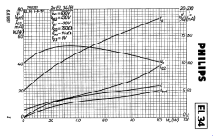
Thanks for the Philips Graph!
No, I will not argue with the Graph.
If I read the graph, I get:
100 Watts Out, Good (Hit the Goal square on the head)!
Plate:
800V x 70 mA = 56 Watts (in two plates that are rated for 50 Watts total, we are short by 6 Watts! Not good)
Screen:
400V, a 750 Ohm series resistor, and 38mA. 750 Ohms x 0.038A = 28.5V drop; 400V - 28.5V = 371.5V
371.5V x 0.038A = 14.1 Watts (Much better, two screens rated at 8 Watts each would max out at 16 watts; We have almost 2 Watts to spare on the screens, Good)
I am trying hard to be fair, but we are over the plate dissipation limit.
Do not forget, those hot plates reflect heat back onto the screen, control grid, and cathode.
56 Watts + 14 Watts (70 Watts) = More than 50 Watts + 16 Watts (66 Watts).
Do not forget the 6.3V x 3A for two filaments, another 18.9 Watts.
70 Watts + 18.9 Watts = 88.9 Watts inside two glass envelopes.
See how this works?
The final outcome:
Distortion:
Sorry, We have 5% total distortion on the graph.
No more than I actually expected (hope springs eternal, there is a fix for that).
Philips graph exceeds their own rules.
And, 5% distortion is a long way from 2% distortion, and even further from 1 % distortion.
Obviously, two things are needed:
1. Negative feedback to get the distortion down to 1%
2. A fan, to extend the life of the hot and overloaded EL34 tubes.
What is the sound of an amplifier that dies prematurely?
The same sound as one hand clapping.
You can see why I was just a little bit skeptical.
Too True to be Good;
or
Too Good to be True.
Last edited:
All quantities in the graph are for 2 tubes. So 55W maximum plate dissipation happening at low power delivery means 27.5W per tube which is the max rating per tube WITH signal (25W without) for the EL34. The EL34 is a much better tube than many think....in ALL aspects.
As I said, your assessment of the cathode feedback effect on distortion is not correct. It might be ok for GRND fbk. Cathode feedback is a LOT more effective at killing non-linearity. Moreover the 5% figure is not the bible, it could be 4% or anything around the datasheet figure, depending on several things. It seems that you never built an amplifier.....
A fan needed? Don't be ridiculous, please. You are sceptical just like those who didn't believe the Earth was round.
Last edited:
So lets actually get some visual about what we are talking about.
From the EL34 datasheet:
https://frank.pocnet.net/sheets/030/e/EL34.pdf
Va: 800V
Vg2:400V
Raa: 11kohm
Ia_bias:25mA
Which results in the following graph:

(https://www.vtadiy.com/loadline-calculators/loadline-calculator/)
Granted, in almost full Class-B mode you can pull a bit more out of the tubes.
But I have a hard time believing that these will have a long life in this mode?
I do think that back in the day they already got a sense of "music power" instead of just continuous output power.
So yeah I can see this working when you consider that the average power of music being played is a lot lower and your amplifier needs to provide the occasional (relatively speaking) peak power.
In the end there is always a time variable in dissipation power (thermal mass inertia).
Meaning that for short periods of time you can actually dissipate more power.
From the EL34 datasheet:
https://frank.pocnet.net/sheets/030/e/EL34.pdf
Va: 800V
Vg2:400V
Raa: 11kohm
Ia_bias:25mA
Which results in the following graph:
(https://www.vtadiy.com/loadline-calculators/loadline-calculator/)
Granted, in almost full Class-B mode you can pull a bit more out of the tubes.
But I have a hard time believing that these will have a long life in this mode?
I do think that back in the day they already got a sense of "music power" instead of just continuous output power.
So yeah I can see this working when you consider that the average power of music being played is a lot lower and your amplifier needs to provide the occasional (relatively speaking) peak power.
In the end there is always a time variable in dissipation power (thermal mass inertia).
Meaning that for short periods of time you can actually dissipate more power.
Yes, the average music power is normally 1-2W region even with small inefficient speakers. They last several thousand hours, it is not a problem in real use.
Have a look at guitar amps. There tubes are much more stressed and last for quite a long time. Often people worry too much about risks and potential problems that in reality have very small chance to happen.
If tubes are tested and selected, no problem. As always, one gets what he pays for.
Instead, the real problem (for me) with the 100W amplifier is size and weight. That's why I prefer the lower power version.
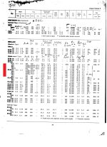
I would also add that many users are correct over querying power tube performance. Sometime ago a friend gave me a box of Russian 6550B plain glass (rather boring to look at with button getters) and on my jig in AB, I darn´t push conditions more than 30W # 450V #60mA (each) was the best with red anodes well established. What do we have here ? I never got this red anode with latter Svetland 6550C´s nor any other with comparable anode size for same operating conditions. Can anyone come to the conclusion that the 6550B is really a very poor mans Btetrode ? These Russian 6550B tubes seem way below what the 6550A or C version is capable of pushing out, and yet there are some marketing ? claims that the B version is also a replacement for the A/C. That is not what I found. Although the B version measuring AB distortion is surprisingly low I would never put these in amps rated over 25W when the original 6550A IMO was a darned good robust tube (42W anode and it mean´t it) and such a pity it is extinct. Comparing tube specs from 60 yrs ago to the same named on todays made tubes, is a case to be on one´s guard.I have never seen the EL34 data sheet that lists the conditions to get 100 Watts power out.
I am sure it exists, but lots of data sheets list more or less information.
From 1960 here it is in tabulated form Class B ICAS (intemittCommercial Amateur Service)... savage conditions as the transmitter modulator amps at that time were modified to be used as PA horn announciators where quality wasn´t required.
rJ
Attachments
See the datasheet that I just posted (above the graph) 🙂I have never seen the EL34 data sheet that lists the conditions to get 100 Watts power out.
This is basically the standard EL34 datasheet as far as I know it.
Otherwise it would not be possible to achieve 100W with two 25W tubes.
Yes. It's even not possible, for sure... At least in a conventional class A or AB1 operation, as found on most of tube power amplifiers. Otherwise, you exceed the maximum ratings of the tube, which is not unusual, of course !
Let's consider a typical double push-pull of 6L6GC (total dissipation circa 30-35W per tube, datasheet) as found on a 100W Fender Twin-Reverb - actual measurements :
- At idle, we have :
Vg=-53.3V/Ik=138mA/Vp=470V. This gives a 34.5mA current and a 16.3W total dissipation per tube.
- At full output power and onset of clipping (86.5WRMS output), we have :
Vg=-51.0V/Ik=422mA/Vp=436V. This gives a 105.5mA current and a 46W total dissipation per tube.
In this case, the four 6L6GC dissipates 184W to produce 86.5WRMS output, which is the usual result for this amp model.
It represents an efficiciency of 47% for a class AB1 operation, which is the norm, not taking into account the heating of the tubes. The total dissipation of the tube is exceeded by 31%.
T
Last edited:
1) Seems you misread the graph. The plate current @ 100W is 91mA per tube.Plate:
800V x 70 mA = 56 Watts (in two plates that are rated for 50 Watts total, we are short by 6 Watts! Not good)
2) Multiplying plate current and B+ gives total consumed power - not plate dissipation.
PD is lower because average plate voltage is significantly lower than B+.
Now lets do the math using datasheet values:
Pin = 2*91mA*775V = 141W
PD = Pin - Pout = 41W
So PD per tube at full output is 20.5W.
Definitely works fine as my old Siemens amp shows.Yes. It's even not possible, for sure...
I's a proven and rugged design also used by some professional Philips amps of the time.
Don't forget that Siemens and Philips both were major tube manufacturers, knowing their tubes.
As said it won't work with 6L6GCs, which need to stay below ~60W.
So no rule between PD and Pout.
Last edited:
That calculator doesn't seem to be correct for this class of operation , 800V ( the idle point ) should be in center and of course the voltage for reactive load goes up to 1600V . Looking at the angle of the load that is impossibleSo lets actually get some visual about what we are talking about.
From the EL34 datasheet:
https://frank.pocnet.net/sheets/030/e/EL34.pdf
Va: 800V
Vg2:400V
Raa: 11kohm
Ia_bias:25mA
Which results in the following graph:
View attachment 1211215
(https://www.vtadiy.com/loadline-calculators/loadline-calculator/)
Granted, in almost full Class-B mode you can pull a bit more out of the tubes.
But I have a hard time believing that these will have a long life in this mode?
I do think that back in the day they already got a sense of "music power" instead of just continuous output power.
So yeah I can see this working when you consider that the average power of music being played is a lot lower and your amplifier needs to provide the occasional (relatively speaking) peak power.
In the end there is always a time variable in dissipation power (thermal mass inertia).
Meaning that for short periods of time you can actually dissipate more power.
Could be, I have made my own excel sheet where I just simply calculate and ax+b graph and when it intercepts with the Pd curve. I haven't checked that yet.That calculator doesn't seem to be correct for this operation , 800V ( the idle point ) should be in center and of course the voltage for reactive load goes up to 1600V
Usually it's in line with this loadline calculator.
One figure is for plate dissipation and the other is output power. In some cases, the output power is 20% of Pd. Other times, the output power is listed near Pd. And when in PP, output power can be well past 200% Pd for one tube or over 100% Pd for two tubes. I am way too new to suggest that the datasheets from GE, RCA, Tung-Sol, etc. are incorrect. I am learning to create my own guitar amp. I have no idea of how guitar amps and home audio amps differ electronically. I do know that guitar heads, like me, want more distortion than home audio people.Not sure if this answers your question as such but it is odd if your a beginner and a valves datasheet says valve X's maximum power dissipation is 25w but then goes on to say later in the datasheet it can do 100w in PP whatever. Measure it's cathode current etc and you'll find it's sitting at 17.5w. Turn the volume up to 3 pop some sounds on and measure the OP at the speaker and you'll find the outcome is 3w.
This is a bit like the small print in a spec sheet for a Foogle XS 100w amplifier saying that the 100w max is only at peak power or "RMS power" or only at 1khz. Get either a valve X PP output stage or the Foogle XS 100, stick a sign wave in and you might get a reading of 100w... but not for long. If you keep pushing either something might go pop or bang.
Like any specification it depends on quite a few other things, for instance we don't listen to sinewave's, then there's quiescent power conditions, speaker efficiency ad infinitum. hope that puts a different take on things.
I would not want to doubt anyone, but from what I've learned so far, it does appear that we ARE listening to sinewaves. Seems as though only sinewaves can make it through capacitors and transformers. And that the signal at the speaker is sinusoidal, causing the speaker cone to move in and out with the amplitude of the A/C signal. Am I wrong about this or were you only being a bit funny considering what we actually hear are variations of air pressure produced from the speaker/s?
Concerning speaker efficiency, I'm just learning that also. I didn't realize the 103db speakers, were so much louder than 90db speakers with the same power applied. My next set of speakers will be at least 102db. Thank you.
- Home
- Amplifiers
- Tubes / Valves
- Tube plate dissipation vs power output